Photos by the author
Part one ended with the completion of the first main building. The part numbers shown on a yellow background. Part two starts with the first wall of the second building, the numbers this time have a blue background and again start with part one.
Rather than just show completed walls I thought that I would try to show how the smaller pieces are put together to make the completed walls. I hope my camera is up to the task of taking reasonable pictures of some very small parts.
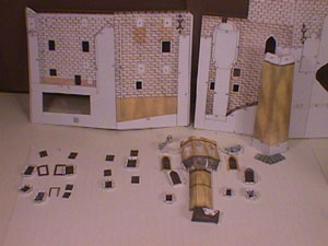
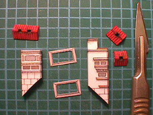
This shows the parts needed to make the first wall. Most of the parts are the windows which need to be folded in such a way that the are recessed to give a pleasing 3 dimensional view. The other main parts are a castelated tower.
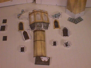
This is a close-up view of the parts that make up the tower. The pieces include three windows, the castelations and roof.
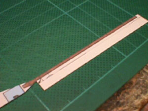
This is one of the many drainpipes that appear on the model. It is a very good example of the detail that is part of this kit. The pipe needs folding along its length so that where is not attached to the wall the pattern is seen on the back. I found that by cutting out the pipe then folding and gluing it left the pipe slightly bent and therefore difficult to trim. I found the best way to do this was to keep as much of the sheet attached. This kept the part straight and once the glue had dried it was an easy task to trim up the pipe.

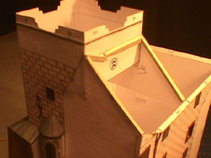
In the first part I mentioned that it was better to leave the recessed windows till last because it was easier to attach the front pieces while the wall was flat. I think this picture shows that I went a bit too far with this idea. I had the towers waving around in the breeze while trying to attach the windows from behind. Despite this I think that this is the best approach because the towers can be fixed more accurately to the walls.

This shot shows how I attach the recessed windows. I put glue on the bottom tab and put it on my table I then put the wall on top, using a pencil or some other item to hold the window in place while manoeuvring the wall. Once the bottom tab has dried it is easy to position the other 3 sides.
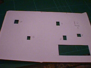
The walls have white squares printed in the window spaces. They have a red cross to indicate that the area should be removed. The white area also has a % sign with a number. This shows that the appropriate part is to be glued from behind. I have a poor memory so I find it reassuring to write the part numbers on the reverse. This also highlights one area where the numerical sequence does not always work. The windows are numbered by size. If there is more than one window the same size then they are all given the same number. So, for example if there is more than one window number 13 one may go on the first wall but the others may have to be left till much latter when the next window has to be attached to wall 77.

This picture is a little difficult to explain. Part 22 is a roof support that connects two walls. Because the kit is printed on one side only, there are small marks on the front with small letters, these marks have to be copied on to the reverse as indicators for the supports position. I use a small pin to make holes on the wall. Turn the piece over and connect the marks with a fine pencil. Some times the area to be marked would show when the model is complete. In these cases the indicators are put on the tabs but the same technique with the pin can be used only this time the pin marks will be in the tabs.

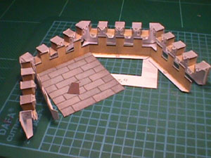
All the main walls have been completed and are attached to the base. There is still a lot of white, which shows there is a long way to go.
If you look carefully, you may note that along the lines that show the roof positions I have added lengths of card. I have found that cutting off the tabs from the roof and gluing the roof to the card makes for a more accurate fit. Effectively the tabs are glued on before the roof!

I try to attach dormer windows and chimneys before I make up the roof parts. In this way you have a firm surface to work with. This time I decided that with so many pieces of roof it would be better to make the roof first. To get a flat surface for the dormer windows, I pushed a12 inch metal ruler under the cutting mat and extending out over my table this gave me a flat surface to work on, much like an ironing board (or so my wife tells me!). Note the fancy cloth under the table. This goes over my lap so if bits fall of the table there is less chance of them getting lost on the floor!

These pieces are for two chimneys.
Part way through making the chimneys, the blade gives an idea of the size
The tower comes next. Here are the eight windows. There are only four numbered parts. This shows that by going from the numbers on the kit you can not check the total number of parts. The "V" shaped pieces are the recessed walls for the windows. The inner tabs are bent forward while the outer tabs are bent back. The windows and shutters are then glued to the inner tabs and the outer tabs are glued to the walls. Refer to picture 16 for my method of attaching the windows to the walls.

Here you can see the completed windows.
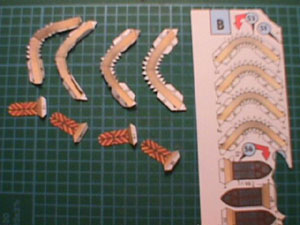
These are the parts that make up the upper parts of the tower. Working from the top. These are the supports for the roof where they hang out over the tower, all 36 of them. The top part has to be bent forward and the bottom part bent back. The two halves are glued together, making sure the top part is not glued. Next come the inner and outer parts for the castelations. The four strips are the pieces that fit between the two walls. Care must be taken to ensure that they are the right way round because the tabs are different for fixing to the outer walls and the inner walls. I also made two card templates to fit inside the tower, one near the bottom and one at the top. The main reason for the top template was to keep the completed castelations flat and square.

In the previous picture you can see the flag mast. This picture shows how I made it. I put a cocktail stick in my mini drill and then put the other end in a small hole I drilled earlier in my table. I held the drill in my left hand and used a craft knife and a sanding stick to shave down the stick.
This gives an idea of work in progress. With no instructions to work with I had to decide whether to glue the four strips to the outside or inside wall first. No prizes for guessing which method I chose. Thankfully this worked well.

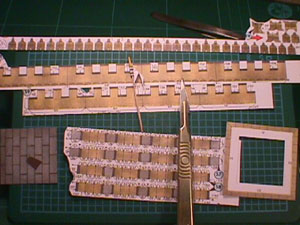
Just an idea of the work needed to add the roof supports. To give an idea of size I included my knife. Don't be mislead, the blade is a 15a which is about half the size of the more usual 15.

One complete tower. I added a small piece of balsa wood under the floor and drilled a hole to support the flag mast. I have not attached this part of the tower to the main building. As with the roof of the other tower, see part one, I will leave it till the end to protect it from damage.
Here ends the second part. The "blue" section is not finished because the next step is to make part of the walls that join the two buildings. The final episode will cover the connecting walls, the courtyard and the finishing touches. This section covers about 23 hours work or pleasure depending on your point of view. Despite the intricacy of some of the steps covered here, all the parts fitted together well. It was really just a matter of painting the exposed edges to complete the assemblies.
