Photos by the author
Part 1 finished with the completion of the first two walls. It was a bit
of a marathon with a lot of detail. This time I will not put in so much detail
but hope to show the amount of detail and immense number of parts for each wall
then jump on to the completed wall and the next step in section A.

1. Here is a tray full of parts for the next section. This is the clock
tower that comes in two parts. You will notice that most of the numbered parts
consist of more than one item. When you consider that there are over 1,400 numbered
parts, you can appreciate the amount of work - or should that be pleasure -
that will go into this project.

2. This shows the underside of the lower roof. It consists of two parts
and as with the other Erkotyp kits I have made, the parts fit is �spot on�.

3. Do you remember Part One? The fingers have grown but the parts have
shrunk. There are four separate vents like this.

4. These are the parts that make up the main dome. This is a good example
of the design skill of Richard Vyskovsky. By adding the tabs at the back the
parts fit together without any tabs showing. Others may have better ideas about
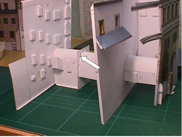
gluing these pieces together, but I glue two parts together so that I have three
parts. I then glue these together, it appears to work!

5. This is the top dome, it is all in one piece but once the score lines
are made the order of gluing becomes reasonably easy.

6. I am quite happy with the completed top. The parts are very small and
need quite a bit of bending and shaping. The whole thing is only about 2 inches
(5 cm) tall.

7. Just another tray of parts���.

8. ...that go together to make this wall. At this point I would like to
remind you of the �audience participation� I mentioned in the first part of
this review. The eagle-eyed may have noticed a pyramid appearing in some of
the pictures. This is a kid's pencil holder that appeared in ABC (magazine).
If anyone is interested in seeing more of it, please send a note via the list
or to the cardmodeller's web site.

9. Don�t worry, this is more of a reminder to mention my recent wood work
project. Before this kit arrived I had decided to revamp my work room by replacing
the desk that I have been using for years. When the kit arrived I realised that
there were so many windows that needed valley folds that I would incorporate
a light box in my new table. As above, if anyone is interested in how I made
it please let me know.

10. Another fuzzy picture I�m afraid. It is here to remind me how lucky
I was. Generally with a line of windows like this I would make a mark through
the card at each end and then score the line on the back. However with the aid
of my new light box I realised that the windows were not in one straight line.
Without the light box a minor disaster would have occurred. If anyone decides
to make this kit, bear this in mind because this happens in other areas.

11. No fingers this time, just another small window!

12. This array of pieces goes to make up the gable on top of the front
wall. There are about 36 pieces shown but there are a few bits that I did not
include. And remember all the pillars needed folding in half and gluing to create
a double thickness. They then needed painting on the exposed edges.

13. This picture shows how Part 141 is glued along the top edge at the
back of the gable and then the �V� shaped piece at the top is glued to part
141. A real fiddle but not too much of a problem. There is a roof section that
covers part 141 at a later stage.

14. This is the finished gable that has been glued to the wall. I have
added some thick card along the join, partly as a strengthener and partly to
keep the area flat. I also added a strip of card between the front and rear
panels. This will help when it comes to attaching the roof.

15. Here we have the main front wall. I have not glued the bits sticking
out at the ends because this are glued to the side walls and I decided to leave
them till the walls were bent to the right angle.

16. In the introduction in part one I said that this kit was really only
a matter of �dressing� each of the walls then gluing them together. I hope this
proves the point.

17. The tunnels are attached to three separate walls. To ensure that the
floor of the tunnels remained flat, I cut off the bottom tabs from the floors
and added a thick strip of card to the wall.
18. The tunnel is now in place. In the first part I mentioned the problem
with the rigidity of the tunnels and the problem with keeping the walls at the
right angle. My idea of not gluing one of the floors to the wall did not work,
so I glued the ends of the tunnels to the outer walls. I then detached the pointed
tabs as shown. This gave me the ability to twist the walls so that they all
aligned with the other walls. The tabs will be re-glued once all the walls are
in place.

19. The final step was to make the roof. Earlier models show that it is easier to glue the parts together before attaching them to the walls. Section A does not create a building with walls on all sides, parts from the next section will �close� the gap. The roof will not be added until I have completed the section and can test the best order for attaching the two buildings and roofs. This ends the first (blue) section. In the next part the numbers will magically change to yellow! See you next time.
