Photos by the author
Part 3 ended with the completion of the first connecting wall, this part will cover the second wall, the "grass" and the bits that have been left off from earlier.

Here I have started the supports for the drawbridge. At the bottom of the picture is a small piece of card that I have cut to the size and shape of the base of the tower. I find it much easier to make items such as the tower and glue a template in the bottom. This keeps the towers shape and also makes it easy to attach it to the base. No fiddling around trying to glue separate tabs. The card is glued to the inside of the tabs so the tower stands flush on the base.
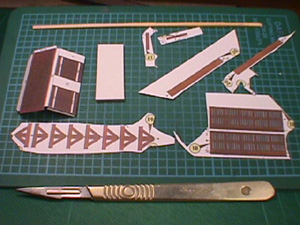
These are the parts to make the drawbridge. The larger piece on the left is made into a thin box. Because this must be kept flat, I cut a piece of card to fit inside. I had to glue two pieces together to get the right thickness. It is then a matter of gluing the piece into shape and sliding the card into the box and sealing the end. The light piece along the top is a piece of wood, shaved to the right size to act as the beams that go underneath.
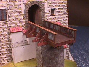
The completed bridge, with the wooden supports just showing at the front. I have to admit that unlike the balcony in the previous article, I left the light blue bits between the balustrades. You will note, there is already some of the ground in place. The two pieces that make up the bank around the bridge support had to be glued to the support before it was glued to the base.
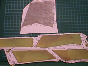
Although there is still one wall to build, the numbers indicate that the "grass" can start to be laid. At first I thought it a bit odd but I found it makes sense because the gap where the wall fits makes it easier to hold the base while doing the landscaping. In all there are about sixteen pieces although the three in front of the last wall are not added until the walls are in place.

This picture shows the ground in progress. The ground pieces are the only parts that are not a perfect fit. I had to make a few alterations and they still left exposed areas of the base. Once the ground had dried I cut off the exposed areas of the base.

Most of the ground pieces have contours. These are indicated by short marks on the edge. The solid lines are hill folds and the dotted ones are the valleys. I did not score the lines but used a thin piece of dowel. For the valley folds I put the dowel on top and gently rolled the piece between my fingers. The dowel joins up the dotted lines on either side of the part. The same goes for the hills but with the dowel underneath.

Here is the piece from the previous picture, precisely placed and perfectly painted. It's not really painted but I had to complete the alliteration! As you can see the fit is not great, but I will be tidying up all the ground when it is complete.

These pieces make up the inner wall of the final side. As you can see, there are more windows and drain pipes and to add a bit of variety there are pieces to make up the sides of the pillars.

The rear view of the completed pillars. The printing on the pillar inserts and the pillar fronts matched exactly. More of a credit to the designers than my gluing! Also a bit of "product placement" for Swann Morton.

This is the completed wall. Again you may notice the bit of thick card along the front. This will be used to attach the floor of the courtyard. I mentioned in part 3 about the benefits of this method. I cut off the tabs and use the card as pre-placed tabs.

A side view of the wall gives a better idea of the positioning of the cloister, it also highlights the thick "positioner" for the courtyard. I have also removed the tops of the drain pipes. I decided that once the wall was in place it would be difficult to glue the roof in place so the roof was added here. The drain pipes needed adjusting so I left them off until I knew the pitch of the roof and therefore the amount of pipe needed for the hopper to be placed properly.

This brings me to the only piece that was not a perfect fit. The wall fitted exactly between the two buildings but as you can see the roof was a little short. I always dry fit pieces first so was able to remedy the problem by gluing a narrow strip under the roof, then painting it to match and then attaching it to the wall.

We are now down to the last wall. Again there are a number of windows a bay window and drain pipes to be made but this time we have some different parts that form the recesses in the wall. Anyone who has made the large-scale cathedrals with the long recessed stained glass windows will be familiar with the construction technique.

For those who are interested, this picture shows the stages for making the recesses. The long side pieces are glued to the flat back, lining up the colours first. Once both sides are glued, the curved top can be glued to the small tabs. I generally put glue on the back then flip it over and lay it on a piece of plastic and gently press the back wall onto the tabs. The recesses are laid face up and the main wall manoeuvred over the top. I put glue on the bottom tab and once it is dry I can then glue the sides and finally the top.

The wall in all is fuzzy glory! In part 3 I mentioned the fit between the two main buildings and the side wall and I can say that I was not disappointed this time. I only had to shave off a small piece from the ground work.
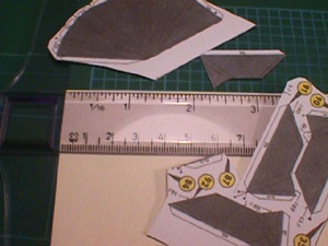
Now that all the main building is completed it is time to make the tower roof. This should have been done in the first stage of the build, but previous experience has shown that these parts are vulnerable to attack from flying arms and sleeves. As an added bonus it also gave me access to the inside of the building which was useful when gluing the connecting wall to the main building. As can be seen, there are four lower roofs and the top. As is my usual method I removed all the tabs, with the exception of the bottom tabs on all five pieces and glued replacements inside each piece. I tried a few methods of putting all the pieces together. I must admit that my first two attempts were not too good. The best method was to glue all the bottom four pieces together. Complete the top piece then slide the "collar" down the tower. I had to shave off some very small amounts of the collar until I had the fit I wanted. It was then a matter of gluing the tabs on the tower to the collar.
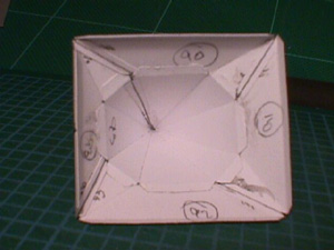
The tower is asymmetrical so it is important to glue all the four bits in the right order and then line up the top part. The tabs on the top part have the number of the lower roof so I scribbled the part numbers on the back of each lower part. You may also be able to see the replacement tabs.
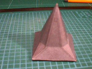
Here is the completed roof. This should be glued to a plate that sits on top of the tower. But as with all this type of situation I make a template that is glued inside the roof and attached to the inside of the tabs. This is described with picture 1 above.
Pics 18,19,21 and 22. The model is complete, at this point I go over the model for the umpteenth time to make sure at there are no white edges and that everything is glued down properly. I also added a few figures to give an idea of the scale of the building.
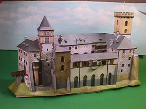


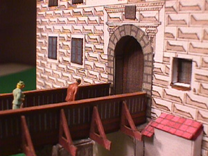
This represents over 80 hours of work. Or should that be pleasure. As you may be able to see from the pictures, the detail is amazing. One item I have not mentioned is the shutters. The instructions show the shutters in an open position against the walls. The parts, however, are made by folding each shutter in half, producing a wooden side and a painted side. The painted side can not be seen if the instructions are followed. So I left some half open and some closed, thus showing off the neat red and yellow pattern. My pictures may not be good enough to appreciate the weathering on the walls but here again, the art work adds a real dimension to the completed model.
It may be a great injustice to the designer because the very few problems are so insignificant, but I will mention two points. The first is that a few of the parts have the wrong part number on their tab when indicating which part is to be glued to the tab. This is no real problem because it is obvious the number is wrong. The second point is the printing. Under the top windows on the building with the flat topped tower, it looks as if there has been printed two extra windows but they have been overprinted. This leaves two discoloured areas. From the research I have made it is impossible to check if this is how the real castle looks or if it is an oversight in the printing.My apologies to the designer if my comments are incorrect.
So, as you can see a few small mistakes on a kit this size is nothing. And anyone who attempts this model will see that this is "nit picking" in the extreme. The attention to detail is excellent and the fit makes this a modeller's dream. If anyone is looking to "take the next step" in their model making I would not hesitate to recommend Erkotyp's Rozmberk.
Finally, my thanks to Joseph Spinelli at http://www.e-papermodels.com who very kindly provided this model for review.
