Photos by the author
Just two months ago Cecil Severs reviewed Marek Pacynski's 1/33 scale model of the P-26A in a well-written and wonderfully photographed article (/archive/2003_February/index.html). He covered the history and specifications fully, and I will not attempt to duplicate his efforts. Rather, this will be somewhat step-by-step review of the manner in which I build 's 1/32 scale model of the same aircraft. I want to thank Mr. Severs for sharing both reference material and photographic know-how with me. He made my task here much lighter.

Kit:
Roman's version is available on CD-ROM at his website (http://digitalnavy.com), and also from PMI (http://papermodels.net/). The model comes in three variations of color, the one that I built, arguably the most famous version from the 17th Pursuit Group, the blue with red 34th Attack Squadron model, and a tan and brown Philippine Air Corps camouflaged variation. I bought my model from PMI's Lou Dausse at a convention a few years back. It was beautifully laser printed with a rather glossy finish that proved durable and looks great. Lou also adds a page of his own written instructions that are helpful. There are 4 pages of printed parts and one detailed assembly drawing.
If you get the PMI version there are a couple of small discrepancies in the written instructions. First, back parts 1-6, 24 and 25 with 1 mm card (Not part 26). The diagram that Roman created shows only one of the landing gear parts 34 doubled to 1 mm on each side. If you don't do it that way - I doubled all four of parts 34 - the parts 35 (landing gear fairings) will not fully cover the back of parts 34. However, the wheels look great with the slight increase in thickness. To solve the problem trim about 1/8" (3.5 mm) or so from the back of parts 34 and sand to a tapered edge. Still glue the parts 34 to the front of the position marked on the underside of the wings.
Preparation:
I used three different glues for this project. Mainly I used Weldbond, an enhanced PVA white glue with a fast grab. When I wanted more adjustment time I used Elmer's Craft Bond clear gel, and I used a Craft Bond Glue Stick for laminating the indicated parts to heavier card. The first two adhesives dry to perfect clarity. This model uses the connecting tab method of construction as opposed to Marek's "butt" type of construction.
Construction:

Start construction by building parts 1 to 6 into a solid frame as shown below. I seem to have cut parts 2 and 3 just the slightest bit large causing a very small gap at the underside when I installed part 19. My advice is to cut these parts just the tiniest bit on the small side. I was probably off by no more than the thickness of normal cardstock. Part 19 requires that you make your own tabs. You can trace the outlines onto paper, as I did, and then notch the tabs when they are installed - below.

The cockpit builds up in a straightforward manner with an excellent diagram supplied. I suppose that you could omit some of the details, but I thought that they added a great deal of charm to the model as seen below. It installs neatly between parts 2 and 3. Part 19 is then added starting with the tab color line on the exact centerline at the bottom.


I really like that Roman makes the outlines of parts, where required, just one pixel thin. The line disappears as you cut, and you're assured that you've cut it to proper size. Once part 19 is in place, below, you will need to get a very sharp blade and cut away the opening. You can then install the coaming - part 49 - as seen below. This part fits beautifully around the opening in a slightly concave shape. I found that the small details in this model tended to fit far better than I could have expected.

Parts 20 and 21are next fastened together with a connecting strip and then to the rear of part 19. Part 22 and its connecting strip are then fastened to the front of 19 followed by part 23 into which 24 has been glued, below. You will eventually need a round toothpick-sized hole in parts 24, 37a, and 19 for the prop shaft. Glue part 37 to part 37a then assemble the cylinders and fasten them as shown. Part 39 is then glued to the front of the motor block, 37a, with the pushrods forming "Vs" between the cylinders, as seen below.


Darken the inside of the cowl, parts 40, 41, and the connecting strip before assembling for a much better appearance. I didn't do this and was unhappy with the look of the engine until I fastened black paper in that area after the cowl was installed - a difficult task. Place the engine assembly inside of the cowl before adhering the motor block to part 24. You can then align the printing exactly and tack glue part 39 to the cowl.
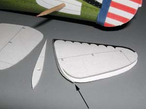
Double parts 30 to about .5-mm (1/64") - they will be much easier to install. See the arrow in the figure below where I have installed most of one. You can see that shaping the part is much easier with some substance. Install the vertical fin support, part 25, and then the vertical and horizontal stabilizers. The fairing for the fin, part 31a, needs to be scored at the front, while the fairings for the horizontal tail, parts 28a, should only be gently rounded at the front.
Doubling part 33a - half of the tail wheel - to 1-mm will make the tailwheel sturdier, cut off the top 1/3 or so or the assembly will be tricky to install.
Another issue which was dealt with on the list - and I forgot about - was the tendency of the airfoil to go slightly concave at the upper trailing edge. Mike Krol suggested using a folded piece of card placed near the trailing edge as a stiff hinge to connect the upper and lower trailing edges. When I contacted Roman he suggested the same thing, and uses that technique on his FW-190. I didn't do this and it caused me some difficulty properly aligning the wing fillets. I ended up with some white showing on the fuselage and went to a craft store to buy a small container of acrylic paint to try and touch it up.
Standing there in a dim aisle in front of a display of glossy acrylics with at least 200 colors I held up my small color sample and muttered to myself that I'd never find a match. A young lad of about 10 years was standing next to me seeking colors for a science project. He glanced at my sample, reached up to the furthest end of the display, and handed me an amazingly good color. Who says that there's no hope for youth?

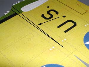
There are two lines at the root end of the wings and only one of them needs to be scored. See my diagram below where I've darkened the lines and indicated which to score. Score this line very lightly.

I added a small card doubler at the front of parts 35 so that I could accomplish the curve I was seeking without damaging the part. I also added a small gluing tab to each of the wheelpants, parts 36, as you can see in the illustrations. This tab really helps close up the top of parts 36 without a struggle. I often add little tabs and reinforcements to my models, but this model required very little help in this regard.
The flower-like part 44 has its "petals" gently curved towards the rear. Part 43 forms into a section of a cone which fits inside part 44 creating all the little holes without having to cut them individually. I glued part 42 to this assembly and fastened the assembly to part 39 for an excellent effect.
I used a toothpick for the front antenna mast. I have a good color photo a P-26A from the same squadron with the mast in black with a white tip. My reference material showed the mast to be thinner than part 48, which I discarded. I used a small piece of a toothpick for the antenna mast on the vertical fin. I used 0.020" (0.5mm) music wire for the flying/landing wires and used silver thread for the antennae. For the flying wires I used a sharp dividers to make holes and measure the distances. I added about 1/8" (3mm) at each end with a small bend. The flying wires assembled far more easily than I anticipated.
I carefully cut out the gun-sight. It seemed so ephemeral that, to give it some dimension, I glued a piece of the music wire to the back. I painted the whole thing with some black acrylic enamel to good effect. It looks good and was far easier to handle with some substance. Lastly, I assembled the prop giving each blade and little "helical" twist and sat back and admired my accomplishment.
Completed Model: I have to agree entirely with Cecil Sever's comments at the end of his article. This was also, for me, the most advanced yet rewarding model that I have built. It sits on top of a small parts cabinet on my worktable and I just smile every time I look at it. This is not at all an overly complex model. The designer has simplified the assembly of this model without losing any of the charm of the original. The parts are numbered from 1 to 53 but with duplicates number only 120.


Summary:
| Model: | Boeing P-26A "Peashooter" |
| Kit: | 3 Color schemes on CD from Digital Navy or individually laser printed from PMI |
| Designers: | Roman Detyna | Scale: | 1/32 |
| Difficulty: | Moderate on the easy side - a great "step-up" model |
| Number of Parts: | 120 |
| Instructions: | CD - diagram only / PMI includes one page of written tips/instructions |
| Fit: | Very good to excellent |
| Coloring and Artwork: | Excellent |
| Printing: | CD - your printer and paper / PMI - excellent glossy laser printing |
