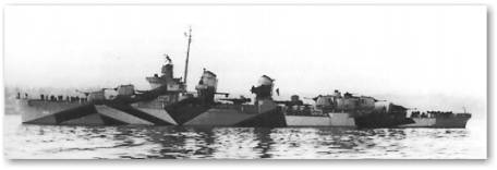

Leutze (DD-481) was laid down 3 June 1941 by Puget Sound Navy Yard, Bremerton, Wash.; launched 29 October 1942.
On 2 August she departed Seattle for the war zone a sleek new destroyer and returned 1 year and 1 day later a battered veteran about to be scrapped. In this short interval she had played a part in five invasions and a major naval battle before a kamikaze ended her fighting days. After departing Seattle, Wash., the destroyer rehearsed in the Hawaiian and Solomon Islands for the invasion of the Palaus. Arriving off Peleliu 12 September (D-3 Day), Leutze bombarded enemy positions ashore and suffered her first casualty when shrapnel from an enemy shell sprayed the ship. Withdrawn on the 24th, she joined TG 77.2 at Manus, Admiralties, for the invasion of the strategically important Philippines.
Action off Leyte began 18 October with little serious opposition to the pre-invasion bombardment but rose to a crescendo climax with the Battle of Leyte Gulf 24 and 26 October. Leutze, first firing on an enemy plane 2 days earlier, suffered 11 casualties on the morning of the 24th when hit during an enemy bombing and strafing run. That night in Surigao Straits with Rear Adm. J. B. Oldendorf's 7th Fleet support ships, she attacked with torpedoes the ships of Japan's Southern Force under Admiral Nishimura. During this phase of the last major battle between surface ships, Admiral Nishimura lost two battleships and three destroyers in a vain attempt to force his way through the Straits and attack the American invasion fleet. Thereafter with its surface fleet decimated, Japan again resorted to air strikes. Although Leutze emerged unscratched, on a single day 1 November, four sister ships of her screen were crashed by suicide planes.
After a period of tender overhaul, she steamed out of Kossol Roads 1 January 1945 for the invasion of Lingayen Gulf, Luzon, Philippines. En route the ship received ice cream for all hands for returning a sailor fallen overboard from Makin Island (CVE-93). She arrived in Lingayen Gulf 6 January for fire support. While supporting this operation, Leutze 7 January sank a Japanese patrol vessel and 9 January a small suicide boat loaded with explosives. Careful preparations were made for the next assault. Iwo Jima, desired as an airfield site, was selected as the target. Practicing with underwater demolition teams at Ulithi and conducting exercises until beyond Saipan Leutze arrived Iwo Jima 16 February. Despite intensive previous bombing and shelling, enemy fire was heavy.
While protecting Navy frogmen on the 17th, she took a shell on the after part of the forward stack. Remaining until the completion of her mission, she then transferred her seriously wounded commanding officer and three other injured and resumed station. Ordered back to Ulithi the next day for repairs, she returned to Iwo Jima early in March but only for 4 days, as much of this fleet was now needed for operation "Iceberg," the conquest of Okinawa.
This last big amphibious operation of the war, unlike Iwo Jima, took place within range of Japanese land-based planes. While escorting battleship New York (BB-34) for the pre-invasion shelling of 27 March, Leutze made two depth charge runs, which apparently sank a midget submarine. On a second voyage with Mobile (CL-63) and Oakland (CL-95), she arrived Okinawa 3 April. This was 2 days after D-Day but in time for the first of the Japanese operations "Ten Go," the massed Kamikaze attacks. Of the first wave to filter through on 8 April, she splashed two and later knocked down a third. Disregarding the danger, she proceeded alongside to assist the thrice hit and burning Newcomb (DD-586). The fourth plane to hit this ship skidded across the deck and exploded its bomb against Leutze's port quarter. The Kamikaze almost severed her fantail and left seven crewmembers missing, one dead, and 30 wounded. Lt. Leon Grabowski, Leutze's acting commanding officer, for his part in aiding Newcomb and in the fighting of his own ship, received the Navy Cross.
Recalling her firefighting parties from Newcomb, she maneuvered clear, brought her flooding under control and was towed to Kerama Retto anchorage for emergency repairs. Departing 10 July via Guam and Pearl Harbor, she reached Hunter's Point Drydocks, San Francisco, 3 August. Following the end of the war, her repairs were halted. Leutze decommissioned 6 December 1945, was struck from the navy Register 3 January 1946, and ultimately purchased for scrap by Thomas Harris, Barker, N.J., 17 June 1947. Leutze received five battle stars for World War II service. (Dictionary of American Naval Fighting Ships Office of the Chief of Naval Operations Naval History Division o Washington.)
The Model:
When I chose this kit I thought that a small 1/200-scale ship could be built in 60 days. Well I was wrong. I almost made it but the details got me; lifeboats, 20mm guns, and a bunch of depth charge canisters all had to be built. A ship model without details is very boring to look at.
I had a few problems when I began to build this kit. It is fair to say that this kit almost broke me. Had I not made the commitment to build this model it would have been headed for the trashcan. However, had I done that, I would have missed out on building a nice ship model.
There are a few design flaws in the kit, which should have been caught and corrected a long time ago. I discovered this while corresponding with Craig Clark from the Cardmodelers mail list. He had posted a few photos of the model he was working on. He had warned me of some of the problems he encountered when building his ship. A few of the printing errors that he mentioned had been corrected since the printing of his version.
The problems I encountered in the model occurred in the beginning of the models construction. Once those were out of the way I was able to enjoy building the remainder of the model.
Builder:---------Federal Shipbuilding Company
Laid Down:------November 14, 1942
Launched:-------March 28, 1943
Commissioned:---May 31, 1943
Fate:-----------Stricken October 1, 1972
Displacement:---2,325 tons (2,924 tons Full load)
Length:---------376 feet 5 inches
Beam:-----------39 feet 7 inches
Draught:--------13 feet 9 inches
Machinery:------Four Babcock & Wilcox
boilers:--------2-shaft G.E.C. geared turbines
Performance:----60,000 shp for 38 knots
Bunkerage:------492 tons
Range:----------6,500 nautical miles at 15 knots
Guns:-----------five 5 inch; four 1.1 inch; four 20 mm
Torpedoes:------ten 21 inch
The Kit:
The kit contains 8 pages of parts printed in four colors red, yellow, black and various shades of gray. There are two pages of building diagrams, as shown in the figures below. The printing and choice of paper are very nicely done. I was very impressed when I first looked over all of the parts.
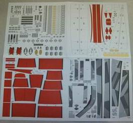
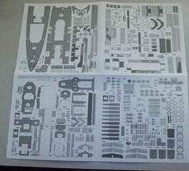

There is a small English insert added to the kit. Although I did not take a photo of it, it can be best described as a minor aid in the construction of the model. It explains a few Polish words such as left and right. It also gives the reader a hint of how to start the model. Other than the diagrams there are no English instructions. The insert also tells of additional material needed to build the model.
A) 1 mm thick card stock is needed for the hull formers and structure .
B) 3/16 or 5 mm diameter wooden dowel rod for the mast.
C) Floral wire for the boat wenches and small cranes.
D) String or fishing line for the antennae's.
E) I will add the suggestion of a surgical tube or needle blank tube for the smaller gun barrels.
Construction:
If you are new to paper modeling or you have a paper model with no instructions, it is generally safe to begin at the beginning. Most card models are designed with parts mating to a consecutive numbered part. For example Item #1 attaches to Item #2. etc. This model follows that scheme.
The main hull structure and outside skins start off with the same numbering system. The diagram shows that each structural former attaches to the corresponding number of outside skin panel.

I started by gluing the internal hull structure or formers to 1mm thick card stock and then cutting out each piece. Shown here on left is the structure of the front hull of the model. Since this was printed on an "A" format paper, the hull is constructed in three sections. The very top piece and the very bottom piece shown in the left hand side picture are the outlines of the side of the ship. They allow the upper and lower hull sections to join along their edge. Each of these pieces has one or two slots cut into them to allow them to join together to form a very rigid framework. At first I was skeptical about how strong it would be. Once I glued them together it made for a very strong and rigged substructure. This held true for the aft section and the fantail of the hull structure.
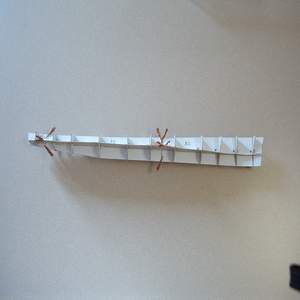
After completing the construction of the three sections, the aft section would then be combined to the front section for a complete hull. This is where I started having problems with the kit. As you can see in the picture to the left, I assembled each of these sections and did a dry fit of the parts. I used small flat-faced copper clips to hold each of the sections together. These came in handy for holding the sub-structure together. They have been mentioned in the card modeling FAQ. They can be purchased at most electronic supply stores.
Since this model is of a full hull there are no flat surfaces to use to hold the model while under construction. Most paper models are water line models. Which means they do not have the full rounded bottom section of the hull. This gives the look of the ship in the water. That kind of ship model allows the builder to glue the model down to a base to ease construction. The construction of a fully rounded hull can be remedied easily by making a cradle out of the scrap material of 1 mm card stock used to cut out the hull formers. If you use an hobby knife to cut out the shape of each hull section, then the opposite mate to that hull section is still intact in the sheet. A simple holding jig can be constructed from those pieces.
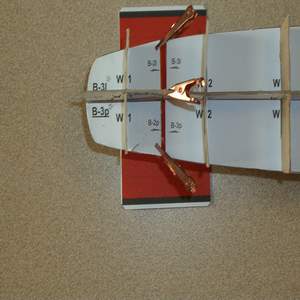
When I went to add the fantail section to the other hull section, the problem of pieces not fitting correctly showed up. As see here in the photo on the left. There is a gap in the horizontal center section of the of about 10 mm. I placed a piece of the red hull section under the piece to help show the gap.

Looking at a side shot of the same area we can see that the keel or spine of the structure mates flush both fore and aft. This brought up the question of "Did I cut something out wrong?" I went back to the sheets and matched up the cut outs to what was given and could not find any other lines or guides that would show I had done something wrong. So the only thing I could do was to continue on.
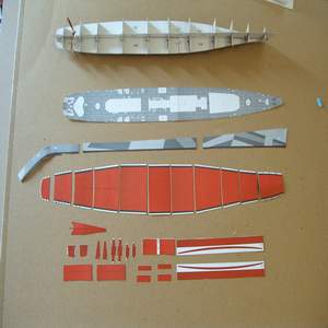
To figure out what was wrong I went ahead and cut out all of the hull pieces.
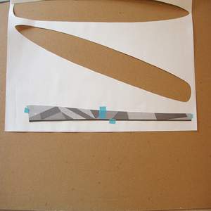
One of the first things that should be done when building a ship model is to double up on the main deck pieces. The reason is it is not strong enough span the gap between formers and stay flat. You will usually not go wrong by laminating a piece of paper the same thickness as the deck pieces. In this case I actually made the deck a triple layer of paper. I took the deck pieces and tapped them together with some non-permanent artist tape. I then used these combined pieces to trace out one large piece of doubling material. By making one piece, I was able to reinforce the seam between the two deck pieces. This is shown here on the left. I am making doublers for the side of the upper hull section. The next photo shows the piece cut out.
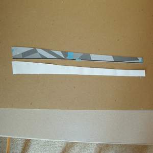
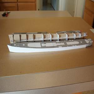
After all of the items were cut out, I made a quick dry fitting build of the outside hull sections and the deck. Once they were built up I compared the length of the hull skins to the deck. The pieces matched perfectly. I then compared the length of the sub structure to the deck. It turned out that the sub structure was too long. I made the assumption that the sub structure needed to be cut down. I went back to where the gap was in the fantail section of the substructure and trimmed off the center vertical piece until it and the horizontal pieces all touched together flush with the other hull sub structure.
After making the necessary cuts, I glued all of the hull sections together with the main deck. I used a thick super glue and accelerator. Since all of the structure would not be seen it would be safe to have some shiny spots of glue here and there. The accelerator also helped by not letting the glue soak through the paper to the outside of the parts. I have found an accelerator that is in aerosol form instead of the manual pump. The aerosol version sends a small fog of accelerator onto an area. It evaporates quickly and does not soak in or saturate the paper. A manual pump accelerator it is not predictable as to how much will come out and were it will go. The droplet size is very large and stains the paper when it hits it. You can find the aerosol accelerator in most beauty supply stores in the artificial fingernail section.

Looking at the substructure you can see that the front structure rises. It is not completely flat. I went ahead and flipped the model over onto the deck to place the bottom rounded hull sections on to the sub structure. Here is a tricky part that got me into trouble when I started on this part of the hull. I laid out each piece to see that they would align with each of the hull formers. Everything looked good as I moved from the front to the back until I got to section ten. It was way off. I skipped that section and dry fit the rest of the hull sections after it and found that the former also affected section 12. Sections 13 and 14 were okay. I had to go back and cut out the bottom-rounded section and reposition it so that it was at the end of section 10 and the beginning of section 11. After seeing that the dry fit of all sections worked out, I began gluing the skins to the structure. It is very important that you take your time in this area. You have three markers to align each of the skins up. The first is the small black line in the middle of each piece. This line is to match the centerline of each former section. The other two markers are the big black lines that are on the outside edge of each piece. They align themselves with the horizontal mid rib that separates the bottom from the upper hull sections. If you misalign any of these makers to the rib station then the next piece will not fit correctly. What is worse is it will snow ball into a big mess where all of the aft sections will not align themselves to their corresponding rib section. Take your time and double check each piece is aligned before you add the next section. The lower hull will go together easily, the upper hull sections are then glued on with no problem and the hull is completed.

The superstructure is next in the assembly of the model. There is one major problem here. It is with Part number 20 Shown.
The front piece that faces the bow of the ship is short by about 3mm. It should be replaced or the piece could be scanned and stretched to the correct length. All of the other sections go together well and the next level of decking has its own doubler built into its design. This provides a strong platform to build off of and no further strengthening is needed.
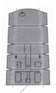
The last major problem with the kit is the design of the 5-inch gun. It is completely too big. Craig Clark has done some work on fixing this problem and has provided a replacement for the 5-inch gun. I built the guns both ways and found his fix to work. Here is the replacement part. I did a cut and paste into word with this picture and printed out several. The only problem is the 5 inch gun on the bow of the ship is a dark gray compared to the other guns.
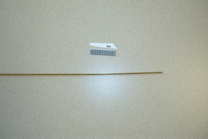
With all of the problems out of the way, it is smooth sailing. The rest of the ship is small details; life rafts, boats, and guns. One small trick I tried was in building the approximately 40 depth charge canisters. They are comprised of a rolled cylinder and two caps. The problem with this is they are small and there are a lot of them. Looking at how they are printed in rows lends itself to simplifying their construction.

I began by cutting out a row of the cylinders. I then took a small brass rod just a hair under the size that they would be rolled into.

I took the cut out and wrapped the whole row at one time..
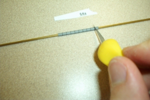
This made a stripped tube.
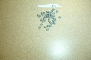
After the glue had dried, I took my knife and slowly rolled it on each of the outlines of the cylinder and cut the pieces out of the tube. By doing this I was able to handle the larger piece as opposed to rolling each cylinder on its own. Also I was able to get the canister completed a lot quicker.
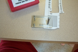
For the end caps I went to my trusty metric punch set. I found a hole that was the same size as the lid to the canister and punched out 80 perfect little circles.
Here are pictures of the completed ship. I added a little detail of the antennas by using monofilament-fishing line. The mast was constructed from a 3/16-dowel rod. I placed it in a power drill and slowly tapered the wood until it was the shape of the mast in the diagram sheet of the kit. I left off the radar that would go on top. It would have gotten in the way of the antenna.
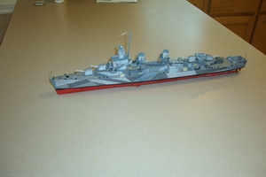
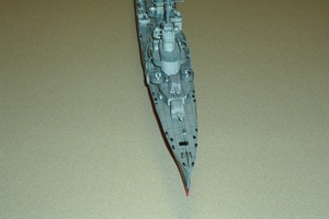
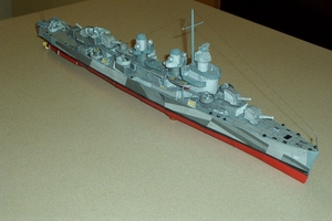
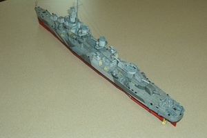
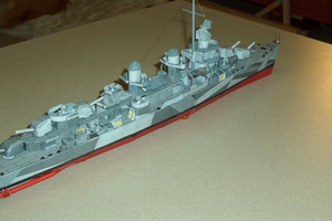

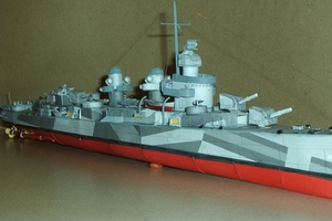


These were the only photos that could be found on the web.
Conclusion: Aside from the initial fit problems of the Hull sub structure, I really enjoyed this model. I would not recommend it as a first time kit, however I would build it again. It is a nice scale to work with and is not that expensive.
I would like to thank Craig Clark for all of his help and labor into redesigning the 5 inch gun piece, and all of the warnings he provided of the pitfalls to be on the lookout for.
Summary:
| Model: | Model: USS Leutze |
| Kit: | Modelik |
| Designers: | Grzegorz Nowak |
| Availability: | Paper Models International (Lou Dausse) at http://www.papermodels.net |
| Scale: | 1:200 |
| Difficulty: | Medium |
| Number of Parts: | Approx 200 |
| Instructions: | Very little in English |
| Diagrams: | 2 pages |
| Fit: | Some problems, 90% of parts fit well |
| Coloring and Artwork: | Very good |
| Printing: | Excellent, nice paper |
| Resources: | Web photos |
 Return to the Main Page