
This model comes on a CD in PDF format. It contains four Pages of assembly illustrations, three pages of parts and one page of accessories. You will need a color printer and card stock to print this model out on. I reccomend that you use 90 lb. Exact Index card stock.
Kudos to Kancho. His design utilizing a fuselage spine interested me from the start. The flowing curves making up Lockheed�s F-104 fuselage are captured nicely. His illustrations are clear and easily understandable. A suggested improvement would be a front view showing the F-104 wing droop not readily seen in the illustrations. A front view would also indicate the gear door strut attachment to the main landing gear.

After a light spray coating of Krylon Crystal Clear Acrylic Coating I cut out the three pages of airplane parts that were printed on 67lb White Hammermill Cover Stock. I reprinted two pages with the fuselage spine 1L and 1R onto 110 lb White Hammermill Card Stock for a stronger fuselage center spine.

As a reminder I colored the mounting sections two places on the spine
for the main gear and horizontal tail piece. These areas must fold outward away from the spine hence we do not want glue there.
NOTE:
If you plan on spraying the completed model with a clear gloss coating
highlight ink might bleed through as well as Sharpie pen ink.

Both Parts 1L and 1R were glued together except for the colored areas The spine was placed onto thick shelf glass, wax paper covered the part and a dictionary for weight was placed on top. I let this dry overnight.

Score the wing leading edges of parts 2L and 2R. Cut the triangles so that they may be folded up when the wing is glued together. The wing is given shape at the root; glue this, the trailing edge, and tip.
Score all the fold lines on the engine parts 3L and 3R. Cut out the wing section. Roll the engine around a pointed dowel or pencil, fold and glue.
Insert and glue the completed wings into 3L and 3R. The wing triangles help make a strong bond.
Glue the wing assemblies to the spine. Notice the wing roots attach high almost near the top of where part 3 is to be glued. This helps establish the wing droop. Start gluing part 3 onto the spine from the front and then following the upper line guide. Once you are happy that the shape is correct glue the bottom. Repeat for the other side. View from directly above and front to be certain both the engine intakes and wings are aligned properly.
Color the inside of the exhaust pipe part 4, roll around a dowel or pencil and glue to shape. Glue to the spine under the vertical fin.

Here is a view of my wire work for the landing gear. I purchased a few lengths of different thickness straight wire all thinner than paper clip wire from our local hardware store. The shape for the main gear worked great. The picture was taken before I finalized the nose gear wire.

Here you can see the development for the nose gear. Once the wire was of the proper length and it fit around the nose wheel I looped the top of the wire so that it could be glued to the spine.

Glue main gear wire into one half of part number 12. Allow to set up before folding and gluing second half.

This is how the tires were formed. The shaft of a small drill was used to wrap the tires and form the main gear and nose wheels. Part number 15
L-1 and L-2, R-1 and R-2, and nose wheel part number 13 were printed on 24lb paper. This made it easy to roll and the finished wheels fit the shaded wheel patterns in the instructions. Glue L1 to L2 and R-1 to R2. When wrapping start with the wide ends of L-1/R1 and wrap while gluing until the narrow ends of L2/R2 finish the tires. I rubbed in glue on the side surfaces
to complete the tires. Glue wheels part numbers 16 L and R to the main tires as shown. Glue part number 14 L and R to the nose tire.

Glue landing gear part number 12 to fold outs on spine as shown in the illustration. Adjust until the wing tips are equal distance above the surface.
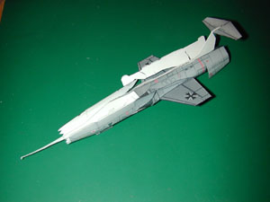
I glued the horizontal control surface part number 9 to the vertical tail fold out tabs when I was checking wing and gear alignment. Add the rear fuselage wrap around part number 5 along with the forward section part number 6. Before being glued to the spine these were curled around a dowel. The nose gear doors were cut open on part number 5 and the center rear of part number 6 was cut to allow sliding it onto the spine. The red line on part number 6 is very noticeable. Be certain this lines up properly. The tighter you get these two parts to fit along the upper spine will render a neater looking model.
Glue tail sides part number 11 L and R to the vertical fin. Again, watch that red line.
Darken the insides and curl the intake cowlings part number 10 L and R. Glue the top surfaces first then curl following down the sides and finish gluing at the bottom.
On the canopy part number 8 slice the rear top center line for the spine attachment. Score and curl as necessary then glue in place.
Nose part 7 curl, score, roll around a pencil point and glue. When it is dry snip enough off its point to allow penetration of the spine needle.
Darken the inside of part number 19 and curl tightly. The curl helps
in gluing it to the left side of the fuselage.
Once the man handling of the fuselage was complete I added the nose gear made up of 17 L and R along with the wire support.
After folding and gluing the hook part number 20 glue it to the bottom right side. I had to look this information up in reference material.
Part number 18 I believe to be an antenna was also checked in reference material. I found a picture with six of those on the bottom of an F-104. Interestingly there are six small rectangles on the bottom of this model right where the antenna belong. I was tempted to add the other five but due to time constraints for the magazine I moved on.
The accessories. The printed out page looked odd to me. My machine had printed this page horizontal on a vertical format and sized to the page. This is kind of late in the game to be checking scale and Kancho did provide a scale on each of his parts pages.

This photograph shows how different the scales were from the aircraft page to the accessory page. I reprinted the accessory page on a horizontal format and still had to increase it 110% to get them to match.

For you craftspeople who are curious here is the parts page scale checked with a steel rule. Oh yes, I�m guilty of wanting to hurry up and build this model. I accepted my printers output without question.

Using a metal rod of the proper thickness helps assembling part number C-1L and R wing tip rockets. The rockets were taken from a printed sheet of 24 lb paper. On part number C-1 L and R slit the lines for the tail fins (part number C-2L and C-3 R) score, then curl and glue together. Score, cut, fold, and glue the tail fins. Attach the tail fins to C1 L and R. Score, cut, fold and glue the fins for the front of C1 part numbers C2R and C3L. Slide them onto the rocket allowing the black nose to stick out and glue.
The four (two for each wing tip) attaching rails part numbers C-4
were taken from a printed 67 lb sheet. This offers more support. Glue the rails to the wingtips as shown. Cut Open the attaching slit on the rocket barrels part number C-1 slide onto the mounting rails, check for alignment and glue.

For under the wings I selected part number B2 L and R. The parts were taken from a 67 lb cover stock. Score, cut, curl around a wood dowel the B 2 barrels. Cut the nose B-1 L and R, roll around a pencil point and glue. Glue B1 L and R to the B2 barrels. When the glue is dry a light sanding with a sanding stick will help shape the nose. Touch up with matching acrylic paint. Slit the two lines for tail fin attachment on part number B 3 L and R score, cut, roll around a pencil point, and glue. Score, cut, fold and glue the tail fins part B 4 L and R. Glue the tail fins to part B3 and then glue B3 to B2 L and R. Glue to the bottom of each wing. There is a light line just inboard of the cross. Finish your model using paints of your choice. I used acrylics and then gave the model a good coat of Krylon Crystal Clear Acrylic.
Summary:
| Model: | Lockheed F-104G Starfighter |
| Kit: | The magic of Kancho's engineering |
| Designers: | Kancho Iliev |
| Availability: | DeWayne Barnett |
| Scale: | 1/72 |
| Difficulty: | Medium |
| Parts: | 30 for airframe and 26 for Accessories |
| Instructions: | Four Pages of assembly illustrations |
| Diagrams: | Very good |
| Fit: | Good |
| Coloring and Artwork: | Good |
| Printing: | Downloaded off my printer. Not too shabby. |
