Kartonowa Flota Atlantic Jamaican
by Dennis Brooks
The Ship:
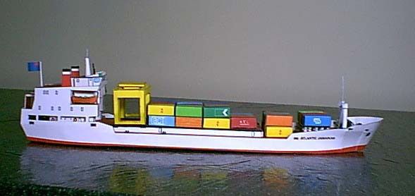
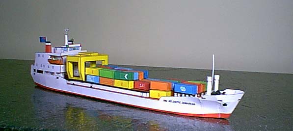
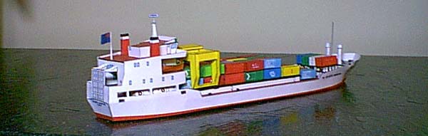
This is the self-loading British registry container ship "Atlantic Jamaican." If I deciphered the Polish well enough, it was built in Holland in 1971. No photos of the actual ship were found, but you can try www.ship-photos.com on the Internet. Iain G B Lovie's photograph list of GBR-Britain (UK)-(Deep Sea vessels) lists the ship under the Associated Container Line. My reading indicates the ship is 85.3 meters long, with a beam of 13.7 meters drawing 4.7 meters of water under way. She carries up to 1345 tons with a range of 3200 Kilometers at a speed of 16 knots. This information is suspect, because I do not read Polish. She is built to load and unload with minimal dock support. There is a large reinforced dropping ramp aft with a rectangular tunnel through the superstructure giving access to the cargo deck. A large rail mounted crane is combined with two support towers and a launder instead of against the foremost containers.
The Model:
KEL is starting a new line of 1/300 scale waterline ship models. Two other ships, the "Albakora" and the "Wostok" are mentioned in the red banner on sheet one. You can find a the Kartonowa Flota series listed on their Internet site as the equivalent of "work in progress." This is also an apt description of this model. The model cannot be built as sent to me. Two of the six major hull sections are proportionately out of size and cannot be "fitted" to build the ship. This is a waterline kit with the hull ending at the point where it would meet the sea as loaded. The kit was apparently a joint effort by Marek Borawski and Marek Pacynski. The kit requires the skills of an advanced beginner to intermediate builder. I base this on the difficulty in constructing small scale cylinders, joining multiple vertical and horizontal bulkheads at one time, and the precision required in building a movable crane over stacks of individual containers.
The Kit:
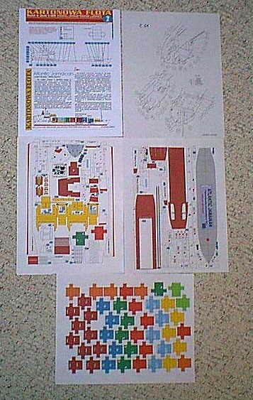
The kit I received consisted of five A4 size sheets. There is a cover sheet. The top half gives general information, construction terms, annotated profile drawing, and blank container for custom painting. The bottom half is a removable tabbed card with information about the ship. The latter allows you to keep a card file of the ships you have built. The second sheet has four more drawings of completed sections of the ship with part numbers indicated. The last three sheets are parts.
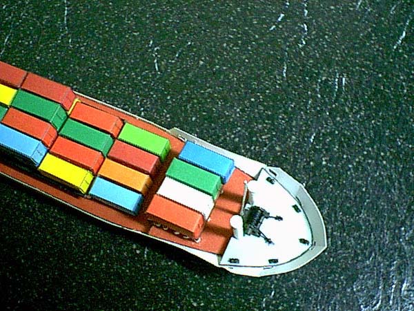
The kit has much to recommend it. It is very colorful with the variety of containers presented. The details include hatches, life rings, life boats with davits, a radar mast, radio mast and detailed caps on the stacks. Even the Kent clear view screen in front of the helm position on the bridge is there. The forward winch and moving crane are well detailed. With two exceptions, the parts fit very well.
Instructions in any language would help. This model has several complex folds and gluing joints that require pre-fitting and a skilled builder to recognize potential problems. The guide to icons indicate a spiral for rolling parts into cylinders (no indication of direction or orientation during rolling), a red asterisk for parts that must be mounted to heavy stock for reinforcement, a green arrow (This is used to link icons to parts, but green lines also tie part numbers to portions of the profile drawing on the first sheet. The second sheet of illustrations is in black and white), black scissors (a short blade and dash indicate cut areas on the parts sheets), a red "W" indicates sections to be removed, and part numbers are black in blue squares. There are a large number of missing icons. A large number of cut marks are missing. No variance in line width or color indicates how far or deep you should cut. There is no indication at all.
Prior to construction, I will cover each sheet for flaws that must be understood to build the ship. Many of the flaws indicate the ship was rushed into production, at least to this stage. Obviously, having the information in your own language would help. English would greatly expand the market. Construction directions and partial build drawings similar to the pictures shown later would be of immense help.
On sheet one the profile diagram shows parts 23 going to the wrong deck. This mistake is repeated in the color profile drawing at the bottom of the page. Both fit on the circles indicated on deck 4. Part 24 is also placed incorrectly. It fits on the circle drawn on deck 1 against bulkhead 4a. These parts are placed correctly on sheet 2 (KF 2). Twice sheet one correctly identifies the ship as the "Atlantic Jamaican", but in the text of the "index" card it is shown as "Atlantic Jamaikan." Sheet two shows "Agtlantic Jamaican" at the top left. The parts sheet shows long sections of the hull parts 7 display "Atlantic Jamaikan", and the stern part 10 again correctly shows "Atlantic Jamaican". I cannot speak to the Polish information given.
On sheet two the drawings are incomplete and inaccurate. The profile drawing of the winch shows the parts out of scale in thickness. Part 31b is shown as a cylinder, but is drawn and indicated as a doubled over plate on the parts sheet. The port part 28 is not ended, the starboard part 28 not labeled. Part 20 is incorrectly drawn twice for the part supplied. A second bisecting loop or disk is shown but not found on the parts sheets. Starboard part 2c is not indicated correctly. Sub assembly 18 is correctly located, but the davits are not shown.
The parts sheet containing the base shows a real need for instructions if this is your first model. The base is not labeled at all. While the lines for the keel and bulkhead supports are clearly drawn, the only icon or number/letter is a doubling asterisk. The part numbers become mixed here. Bulkhead deck supports 1a are part of the Alpha lettered egg crate support structure, but are numbered to be put into place after the deck, 1b is placed on the completed egg crate. Appropriate placement is indicated on parts B3 and B7, but orientation fore and aft are not. Since these support sections must face each other to mount deck 1, you must place B3 or B7 in opposite orientation to all other bulkheads of the egg crate for both sets of supports to face inward. Both 1a placement marks are dotted lines in black. Perhaps one should be in red indicating placement on the rear of the piece. All of the egg crate parts have notches for the hatches on parts 2a have hinges while those on parts 5 and 13 do not. This is an indicator of incomplete drawing or hurrying to finish. Part 1b is placed as shown on deck 1 to reinforce the end of the raised rail deck. One placement area, starboard forward, for parts 1c is colored in. The part 1c, a bollard set, should be mounted there. Parts 4b intersect and are partially covered by the base plate. Two of the five parts cannot be used as drawn.
The parts sheet with the bright yellow crane is missing a number of cut indicators and here the direction of folds is essential for beginners. Due to the orientation and packing of the parts, the cut indicators on part 30 are offset from the cut line. The only indication of how deep to cut is to stop where the line hits a corner. Part 31b is shown as a rolled cylinder on drawings sheet KF 2, but here it is not marked with the spiral icon. There is a white overlap flap. However, the same style overlap flap on part 31a is nothing more than a doubler. Lines are the only indicators of folds. On the crane you can refer to the photos below for assembly. This is one drawing essential for construction that KEL left off. They show the sliding winch head, but not the crane supporting structure. The davits in sub unit 18 are folded to form the curved mounts. There is no indication of how to mount the lifeboats to the dhe roll of the cylinders and the overlap of the extended areas to form a thick "cap side" at the top of the cylinder. Part 23 is also missing the cut lines for the flap forming the bottom of the cylinder. Part 17 has multiple fold changes that become apparent when attaching it to part 16. Note the green container is missing the overlap flaps on one end square. The "W" marks, up by the ship's name on each piece, on parts 7 should be red indicating removal of the small rectangles.
The parts sheet of containers has fold flaps missing from two dark green containers on the square ends. These are dense packed parts and care should be taken in cutting them out. The irregular shapes do not lend themselves to cutting with a ruler and knife. I uses sharp tip craft scissors. There are 12 fold lines to each container. These folds must be precise to form the rectangles so they will stack and fit between the raised rails on the deck and the arms of the moving crane.
Construction:
This is a typical base and egg crate support structure for a waterline kit. My first step is to cut out all of the parts marked by a red asterisk for doubling or mounting on heavy stock.Note: I bought a cheap but extensive set of coloring pens to color the edges of all the parts on this model as I cut them out, including doubled pieces. With the extensive range of colors among the containers, a large selection was required. A comparative photo will show you just how many white edges would show to mar the finished model without this step.
I received the kit on CD and was able to double print, then glue back to back, the pieces on the 110 LB card stock that I typically use. This gave me the lines to mount the egg crate and deck supports 1a while providing the thickened parts. It also leaves the label information on the base exposed if you lift the ship. It is in Polish and the ship's name is again incorrect, but a nice to have feature. If you receive a printed kit, you will need to put these parts on backing material thick enough for the crossing parts to fit snugly in the egg crate notches. This also provides decks thick enough to line up with the other parts. You will have to add an additional layer to the base for the hull sides to fit flush. Even with the base doubled, all six hull pieces extended one thickness further down. If you receive the kit preprinted, cut the parts with space outside the lines. Glue shrinks when drying. You can trim to the lines after the pieces are dry.
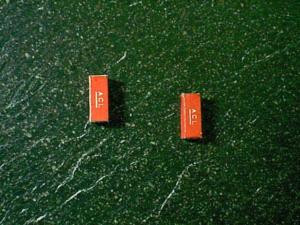
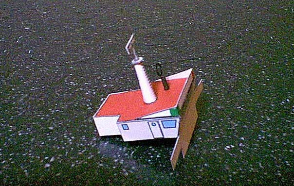
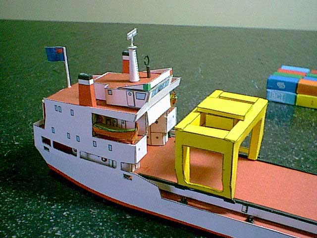
Note that you can build sub units 18, 19, 22, 23, the crane parts 30-31e and containers at any time while other parts are drying. This means the sub units will be ready when you need them, saving time. Building the containers and maintaining quality is tedious and should be done a bit at a time. I built five or six at a time between other parts or while watching TV. I cut them all out, colored the edges with matching coloring pens, creased all 12 folds on each with a metal ruler and metal rod, then stacked them by my chair and assembled them as the time and urge permitted. The crane is a real piece of work with the sliding winch platform. Building that without directions or diagram is not for a beginner. The photos show the complex cutting and folding to end up with the crane. It must be precise to ride the rails on the deck and clear the stacked containers. The winch is not shown either.
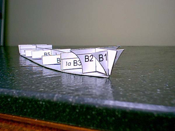
Once dry, I tack the base to a flat surface to keep the structure stable. Any errors from the base up are multiplied by the distance to the top and outsides of the models. Small errors can become very noticeable. I assembled the keel A to the cross supports B1-9 from front to back. It is very important to keep the tops and bottoms level between the keel and cross supports. Dry fit each piece and cut the notches as required to insure the tops and bottoms of the keel A and the cross supports B line up exactly. There is enough flexibility in the paper to start at one end of the base and add cross supports one at a time gluing as you go. I tend to cut just outside the lines on top then use a fingernail sanding board to sand flat once mounted to the base. The parts fit together well and little sanding was required on each deck level to insure they were flat. I added section B10 last.
You can start out building the ship by the numbers on the parts. I checked the fit and laid the decks 1 through 4 to the structure. Again I used the sanding board to finish the edges to the structure, straight where required, and removed any leftover extruded glue. Bulkheads 2a, 3a, 4a are added. You can add the ladders 2c and 3b now or later. I chose later to avoid possible damage. The bollard plates 1c, 2b, and 4b are all doubled and the edges should be colored before putting into place. You will see that I delayed putting them on. Being a bit crazy (an ex-helicopter pilot), I rolled paper stock into a long thin cylinder painted black with coloring pen. I sized the cylinder to match the circles on the plates indicating the posts. I cut minute semi-scale lengths to form the 3D bollards and glued them on using a sewing pin to apply glue. Since they were delicate, I added them as I finished sections of the ship. Photo of parts 5 front and back
Parts 5 were cut as indicated to form the lifeboat decks. I followed the outline on deck piece 2 marked 8P/8L to form the lower segments of parts 5. The lines on the lower bulkhead section form right to the pattern. I sanded the edges of parts 6 to remove excess paper and glue and mounted them on the lower bulkhead section of part 5, gluing them to the second level bulkhead sides. This is where some experience is required. First you must see the piece folded without diagram or directions (the complete drawings on KF 2 don't help a lot), then you glue multiple vertical and horizontal surfaces at one time insuring parts 6 are parallel to part 2 and meet the top edges of lower parts 5 and bottom edges of middle parts 5. The photos should help you see how these pieces fit. The ends of parts 6 must be even for the hull parts and ramp to match and meet. You will see in the photos that I built one part 5 and 6.
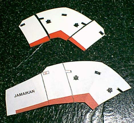

At this point I was fortunate to be proficient with Adobe Photoshop Elements. I opened the parts page and copied three pieces out to a work file. I took the bow section part 9, the front portion of one side part 7 and the larger part 8 and placed them on a new file work surface at the same resolution as the original. Using rotate and movement tools I lined the three pieces up. I then proportionally resized part 8 down to line up with the other two hull sections. Reducing the part size did bring the lines, rectangle cutout and lower red segments into line. I then cut the resized part 8 from my work surface, made a copy reversed horizontally, and pasted the two new parts 8 onto the parts page. I had to reprint the entire page to make sure everything was in scale. Had I known of the problem to start with, this would have been my copy for doubling parts 4, 11, 12 16 and 22!

I was now able to add parts 8 to part 9 the bow, one side 7 and place part 10 across the stern. I used a white gel pen to help hide the black lines where the parts joined. You cannot cut inside the lines for all white parts. They will not fit around the base structure and decks! Here I departed slightly from the "follow the numbers" assembly. I added part 13 to join and square parts 5 before adding more parts. Part 11 is the reason I left off the second hull side part 7. Part 11 forms the top of the tunnel through the superstructure and must be placed flat while insuring the interior sides of part 5 are vertical. This keeps the superstructure square to the deck. It made sense to me to put sub units 18, the life boats on davits in while parts 5 were still uncovered. I joined the lifeboats to the davits with "button hole twist" weight thread rather than glue direct. Now I finally added the second hull.
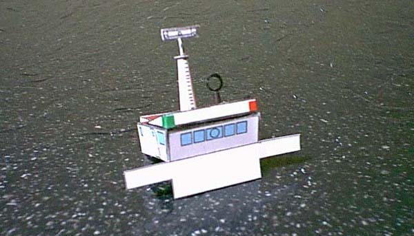
I built the bridge as a separate structure using sub units and parts 14 through 17, 19 and 20. This fit into place on the superstructure without problem. I added parts 21 the stacks to complete the superstructure.
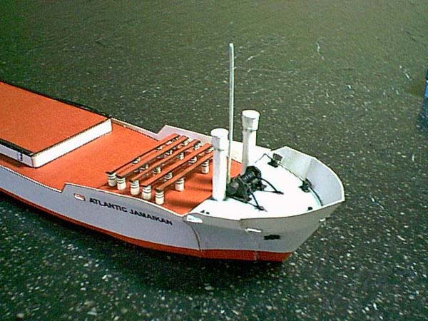
I finished adding parts 4b, parts 23 and sub unit 22 where indicated on deck 4. I doubled part 24 the mast for strength and because I had the second piece. I glued part 24, parts 26 and parts 27 in place on deck 3 as indicated on the deck and page KF 2. I cut parts 25 the doubled rails out very carefully. They are sized to fit on the railed deck and have four containers fit in between. Be sure to glue them directly over the marks on part 2.

Trim part 29 the rear ramp if necessary to fit between the rear bulkheads. Glue on parts 28 ramp braces then part 29, joining the deck to the upper ramp braces. I trimmed the surface off the card stock to get a translucent piece with the flag part 32 on it. When folded and glued it was thinner than normal 20 LB copy paper. You can fold the card stock, print on thinner paper, or what suits you. I used scrap to make a flag staff since one is shown but not provided in the parts. I centered it on the back edge of part 12 the upper deck and glued it in place.
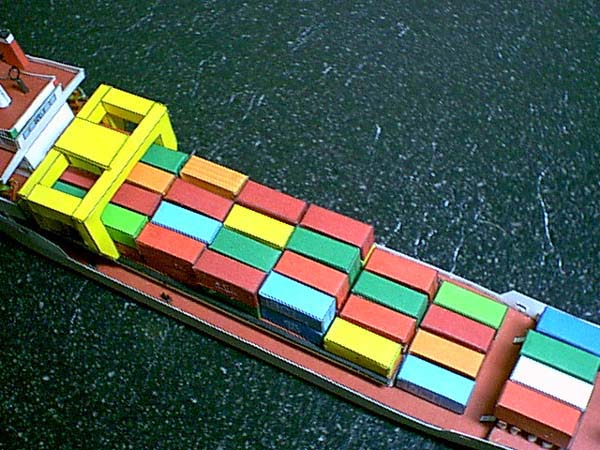
Stacking the containers and placing the crane in position finishes the ship. Personally, I use a "Stick It" tacking glue stick to join the containers. Touching the ship causes them to topple. Once you decide on a pattern, you can tack with this or rubber cement. If you are satisfied, you can permanently glue the containers in blocks of your choice. It would not hurt the kit if KEL made a long rectangle and two short ones that had the containers printed in pre-stacked sets for the rail deck, main deck, and rack. A lot shorter build time!
Conclusion:
KEL has shown a lot of potential in this ship. Other than the hull pieces, the kit fit together well. It has an exaggerated parts count with all the individual containers. The detailing is excellent. Not many ships this scale have all the vents and exhausts detailed on the top of the stacks. The crane winch slides back and forth and the entire crane moves up and down the rail deck without problem. This shows how well the kit fit from the base up. I did not have to trim and fit the parts to get this to work. There is a lot of fine hand work in a 1/300 scale with this many details. I think the kit will be a real addition with all the color to any collection. The scale would place it in the middle of a 3D diorama between the 1/250 and 1/400. It needs better diagrams and some directions would not hurt. Translation to English would really enhance the appeal.

Summary:
Once KEL resizes parts 8 of the hull I would recommend this model to any intermediate or above modeler. It would take an experienced and advanced "beginner" to build this scale well with these fine details. I enjoyed building the ship. I found the containers tedious. I would build others from KEL and recommend them if the parts fit as well as this model. I was truly impressed to have the crane fit on the rails and over the containers without some type of adjustments. I have a large library of photos during the build and I have a number of building tips that will go to appropriate places in the magazine. If you would like some color added to your fleet this is a great choice.
| Model: | British Container Ship "Atlantic Jamaican" |
| Kit: | Kartonowa Flota |
| Designers: | Marek Borawski ∓ Marek Pacynski |
| Availability: | http://www.kel.frame.pl |
| Scale: | 1:300 |
| Difficulty: | Currently - Expert with Adobe software experience; With New Hull Parts - Advanced Beginner and Above |
| Number of Parts: | 217 (47 containers 43 backing pieces, and 127 parts to the ship) |
| Instructions: | Diagrams only |
| Diagrams: | One profile, one bow, two (front and back) of the superstructure. Several mistakes. |
| Fit: | Excellent (exception: two hull parts I would expect to be changed) |
| Coloring and Artwork: | Exceptional, especially for this scale. Very colorful scheme with containers. |
| Printing: | Printed from emailed zipped PDF file using an HP Deskjet 952 printer on 110 LB White Georgia Pacific mat finish card stock on normal print setting (600 DPI). Converted from A4 to US letter format (94.1%) 8.5 by 11 inches (216 by 279 mm). Could be printed full A4 using paper spacing strips taped to the top of the card stock. |
| Resources: | Ship Photographs |
