


Clink on the link below to see the review of that model.
PMI P-39 Airacobra
Modelcard Seversky P-35
ModelArt A6M3 Zero
Fly Model I16 "Rata"
Halinski's Messerschmitt Bf-109E ("Emil")
| Model: | Bell P-39 Airacobra |
| Kit: | PMI 109 (Paper Models International) |
| Scale: | 1/32 |
| Price: | US$ 6.95 plus S&H from PMI |
| Difficulty: | Medium (3 out of 5) |
| Number of parts: | About 85 |
| Instructions: | Good |
| Diagrams: | Good (wire templates and a photo of the finished model are needed) |
| Fit: | Very good |
| Coloring: | Very good |
| Resources: | Some good photos can be found at The Russian Air Force Museum site at: http://hep2.physics.arizona.edu/~savin/ram/p-39aira.html. It has a number of links to other sites with good photos. There is also some photographic and background information at the US Air Force Museum site at http://www.wpafb.af.mil/museum/air_power/ap1.htm |
This was my first try at a large plane since returning to card modeling after about 15 years. Id tried a couple of the smaller planes from Fiddlers Green and Fabrizio Prudenziatis site, as well as the V108 from Digital Navy. I thought it was time to try a commercially produced model in a larger scale, and chose the P-39 which has always been one of my favorites because of its sleek lines and unusual design. The Airacobras performance was compromised by some very ill-advised, cost-driven engineering decisions, and it gained a poor reputation as a fighter among U.S. pilots (who nicknamed it the Iron Dog). One of those engineering decisions was to eliminate the supercharger included in the original design, which ruined the P-39s performance above 17,000 feet. On the Eastern Front, however, its heavy armor and large cannon served the Soviet forces very well in a ground attack role. And I still think it was one of the most beautiful planes produced during the war.
Since this was my first go at a commercial hardcopy kit, where I didnt have the luxury of limitless replacements for my mistakes, this review is going to be as much an account of my own learning experience as it will a review of the kit itself. Perhaps this will help other beginners. Theres a tremendous number of P-39 related resources on the Web, and I did use many photos pulled form the Internet for help with details of parts shaping and placement, antenna rigging, and other minutiae that were not clear from the kit drawings and instructions (see Resources, above, for some starting points).
The kit itself is simple but well done, with about 80-90 parts overall (depending upon how you count things like exhaust louvers), all printed on a semi-gloss paper that is very easy to work with. The design and markings appear to be accurate. One minor complaint might be that the panel markings are fairly pronounced for a model of this size and scale. With few exceptions, fit was very good, with only minor rework necessary. Instructions and diagrams were easy to follow. Full-size templates for wire parts would have been helpful, however, as would photos of the finished model.
The fuselage uses bulkhead and strip construction. The connecting strips are colored, which helps to minimize the impact of slight alignment problems. The instructions caution you about making sure that the fuselage skin, bulkhead formers and strips are correctly sized before gluing. The importance of this warning became immediately apparent with the first few fuselage sections, one or two of which began taking on an hourglass shape. Time to remember some high school math. An error in the diameter of the bulkhead former of a third of a millimeter (little more than the width of the lines used to draw them) will result in almost a one millimeter gap (or overlap) where the edges of the skin butt together. (The circumference of a circle, even one thats slightly ovoid, is approximately 3 times the diameter.) And that third of a millimeter is just about the difference between cutting on the inside or outside of the line used to draw the part! The lesson is to cut the bulkhead a little on the large side (on the outside of the line), and then sand it down until everything fits. Ive found that 3M removable tape (which uses Post-It adhesive) works extremely well for holding the skin together while adjusting the bulkhead former and test-fitting the part. Single-sided and double-sided removable Scotch tape are now a permanent part of my toolkit.
Dont forget to put the nose weight in section #5 before you glue the sections together. I forgot, and ended up having to feed little pieces of solder through the machine gun mounting holes in order to get the nose to stay down.
Empennage assembly was straightforward, though minor adjustments of outline were needed to match the opposing surfaces of rudder and stabilizer.
Wing construction uses a spar with two ribs, one near the root and one near the tip, and a long gluing tab at the trailing edge. This produces a cleaner trailing edge, but requires that the wing be kept perfectly flat during construction and drying. Be careful to insure that the outline of the spar does not cause a bulge in the upper or lower wing skin which is especially likely near the wingtip. This is also a good time to do some advance preparation for the landing gear installation. A small piece of Styrofoam glued where the landing gear strut (wire or toothpick) will be mounted would help; or you could glue a piece of thick card to the top of the wing where the strut will contact it. Either method will help avoid the strut raising a bump on the top of the wing when installed.
Fitting the wing root to the fuselage was a bit of a problem, though I think that may have been due more to inexperience than anything else (and failure to do a good job of dryfitting before final wing assembly). Some judicious restyling of the trailing edge of the wing root where it joins the fuselage, and careful application of the wing fillet helped to disguise the problem.
Landing gear assembly was not difficult. I used piano wire (.032 or .8 mm) rather than toothpicks for the struts, and followed the diagrams in the instructions for shaping. Full size templates would have helped, however. Wheels were built up with extra layers of card stock, sanded to shape, and colored with a dark gray marking pen. There is a potential problem, however, with the wire for the main gear struts producing a bump on the upper surface of the wings. This could be avoided by following one of the suggestions mentioned above. I didnt do this, and have to be very careful about putting any weight on the plane.
I like the way the propellers are done. The shaft end is completely rounded, with an airfoil formed into the blade. A back is glued onto each blade, and the assembly is then glued to the prop shaft (a toothpick), which also serves as the nose cannon. A little sanding and coloring of the glued edges is required, but the result is very realistic. Wing guns were easily rolled from the paper provided. Nose wheel doors were correctly drawn, but the scribing on the fuselage was incorrect; the small chamfer on the trailing edge of the doors belongs where they join together (as the doors are drawn), not where they are hinged to the fuselage (as the outline of the wheel well is drawn). This is a problem only for those who pick up the model to inspect the underside in detail.
There were no problems with the cockpit canopy, using the thin acetate material supplied with the kit. I used cyanoacrylate glue to tack it in place on the canopy frame. I did have a problem with the air scoop just aft of the canopy. On the real P-39 it hugged the fuselage closely, but on the model it sits up too high, and a rounder shape than it should. This could have been fixed by dryfitting and adjusting before gluing which I failed to do.
Figuring out how to string the antenna wire turned out to be a challenge. Nothing in the kit, and none of the photos I could find, were clear on how the antenna wire was to be run on this version of the P-39. I finally found one picture that suggested that the wire should be run from the tail to the antenna mast, and from there to the main brace on the cockpit. This is how I wired it, though Im still not convinced that its correct. I used .005 (.013 mm) gray transparent nylon thread, painted gunmetal black. With the paint covering, the antenna is approximately to scale for a 1:32 model.
I used watercolors to tint all exposed edges. I actually used watercolor pencils, but with a fine sable brush to pick up and apply the paint.
A couple of other observations:
1. It would have been good to build in more cockpit detail, especially given the large transparent canopy. The radio stack behind the pilots seat would be easy to scratchbuild, for example, and more control panel and flight control detail could be added.
2. I used cyanoacrylate (CYA) glue to tack several external parts into place, and found that it really discolors the printed surface of the model if its not applied with the utmost care. The very thick, slow-drying CYA glue is probably okay, but the thin, instant cure glue will create problems. (Notice the nose gear door in the photos.) I had a similar problem with a dark gray artists marker. The ink bled through the paper and discolored the painted surface.
3. I found a great burnishing tool in an art supply store, and it helped in rounding and smoothing the edges between fuselage sections, the trailing edges of the wing, and rounded edges in general. Im not sure what the tool is for in real life, but it has a large curved polished metal surface, and I found it in an art supply store near the block print section.
4. Color all unprinted surfaces that will be visible when the model is complete, including those that are inside the aircraft. I did a pretty good job on the outside, but failed to color the inside of the cockpit framing, for example. After you glue the canopy in place its too late.
All in all, it was not a difficult model to make, a good starting point for an experienced beginner someone thats learned the basics of score, fold, cut and paste. I was really worried about what the finished model was going to look like as I piled one small mistake (read lesson learned) on top of another. But the end result is actually very satisfying. The overall impression outweighs the accumulated mistakes by far.
Bill Geoghegan

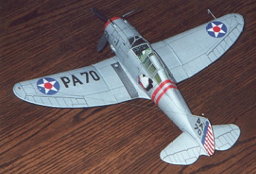
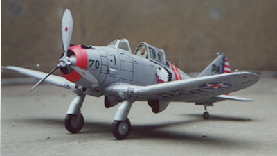

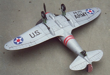
| Model: | Seversky P-35 |
| Kit: | Modelik 5/98 |
| Scale: | 1/33 |
| Price: | US$ 5.95 plus S&H from PMI |
| Difficulty: | Medium (3 out of 5) |
| Number of parts: | Approximately 120 |
| Instructions: | Poor. Only a quarter page (half of one column) in Polish |
| Diagrams: | Fair. Drawings were sometimes inaccurate: e.g., the fuselage tail cone (part #7) was not shown on any drawing. A photo or two of the completed model would help. |
| Fit: | Good |
| Coloring: | Very good. |
| Resources: | A series of excellent closeup photos of the sole surviving P-35 (a P-35A variant sold to Sweden before the War), housed in the Swedish Air Force Museum at Linköping, can be found on the IPMS Stockholm Web site at: http://www.hotel.wineasy.se/ipms/stuff_eng_detail_p35.htm. There are also some excellent photos, specs and background information on the US Air Force Museum site at http://www.wpafb.af.mil/museum/research/p35.htm. Rick Kent's Fauconberg Aerographics profile site has a drawing of a P-35A that shows the antenna rigging detail to advantage. Try http://members.aol.com/fauconberg/a0125.htm. |
Background:
The Seversky P-35 was the USAAC's first all-metal fighter with an
enclosed cockpit and retractable landing gear. Introduced in 1937, it was a direct ancestor of the Republic P-47, whose evolution can easily be seen by comparing the P-35, XP-41, P-43, and P-47 (photos available on the USAF Museum site). The company was renamed "Republic Aviation" when Seversky left in 1939. The USAAC ordered 76 of the original P-35's, all but one of which were assigned to the 1st Pursuit Group in Selfidge, Michigan. The Modelik P-35 is based on one of these. The Japanese Navy received 20 P-35's in a two-seat version in 1938; and as a consequence the P-35 enjoyed the dubious distinction of being the only American built warplane to see operational service with the Japanese during World War II. A slightly improved version (designated P-35A by the Army) was provided to Sweden just before the War. An initial shipment of 60 was delivered, one of which now survives in near mint condition in the Swedish Air Force museum. A second shipment of 60 was embargoed and seized by the U.S. in 1940. Most of these were sent to the Philippines, where all were lost in action early in the Pacific war.
The Modelik kit:
Modelik's P-35 is printed on good quality card stock, using a semi-metallic ink for the unpainted metal surfaces. This ink is almost impossible to reproduce with any standard model paints, and attempts to fix anything but very small blemishes will be obvious. The sheet of bulkheads, formers, etc., needs to be backed with cardboard or cardstock to a thickness of 1 mm. I used several layers of thick posterboard, which worked adequately. There are lots of parts whose unprinted sides will show in the finished model, and these need to be colored before assembly. This is especially true if you choose to use a transparent or open cockpit. The inside surfaces of the cowling should be colored a dirty black (dark grey); inside surfaces of the cockpit framing need to be given a zinc chromate coloring; the deck aft of the pilot's seat also needs coloring (it's white, as printed, instead of zinc chromate); and all landing gear housings and fairings need to be colored where visible. I used Testor's zinc chromate for small sections. For the large area of white behind the pilot's seat, I used Paint Shop Pro to print a large zinc chromate rectangle. I cut pieces of this to be used as needed. This gives a smoother finish than one can get by using model paints on large paper surfaces.
Fuselage:
The kit uses the butt-joined cylinder method of construction. Fit is generally good, but it is important to dryfit and adjust everything before gluing. Adjoining bulkheads have to be matched for shape, and adjusted to make sure the covering skins fit perfectly. Mistakes can cascade, so each section has to be made in conjunction with its neighbor to avoid problems. Note: the tail cone (part #7) is shown on none of the drawings; it should be formed and glued to the aft end of cylinder #6. 3M removable "Scotch" tape was a godsend for dryfitting.
Cockpit assembly is straightforward, though the pilot's seat is a little too high and needs to be shortened slightly. I used brass wire and paper to make the control stick. I took scrap pieces from the backed (1 mm) sheet and made a cushion and headrest (painted brown) to glue on the seat. I did not install the canopy until much later in construction, when less handling of the fuselage would be needed. There's a good cockpit interior photo on the USAF Museum site.
Assembly of the gun ports on the cowling is incorrect in the instructions, which show the shape of the cowl opening reversed from what is actually printed on the model. I took two pieces of stock, painted aluminum and formed into half cylinders, and glued them into place below the gun cutouts on the inside of cylinder 1. Don't try the arrangement shown in the drawings. It won't work.
Empennage:
Empennage assembly was straightforward. Just like the main wings, the stabilizer and rudder each have trailing edge formers cut from 1 mm reinforced stock. I sanded these down along the trailing edge and glued them into place with an offset of about .5 mm (this required some additional shaping of the former). This gave a better taper to the trailing edges, and it allowed me to smooth and round the printed skin around the tapered former and then glue it shut. This gives a much more finished look to the edge, especially where edge coloring is impractical (aluminum surfaces, red and white striping on the tail, etc.).
Wing:
The port and starboard wings are constructed of two parts each, with all dihedral in the outer portion. The outer wing section is formed around a single inboard rib, a tapered box with interior spar, and outer tip and trailing edge former. Positioning is not all that clear from the diagrams, so common sense (and lots of dry fitting) should be the guide. The rib seemed too short as drawn, and I had to use some extra material to make it fit more snugly with the skin. I treated the former and skin as described above.
The inboard section of the wing is a problem. The ribs are a little too small and need some build-up. But the biggest problem is a serious mismatch between the length of the wing roots where they join on the bottom and the space marked for them on the fuselage, which is about 1/4" to 3/8" (.8cm to 1cm) too long. I got it fitted after a while, but had to paint a large section of the underside of the fuselage to eliminate the white area exposed by the mismatch. The wing root fairings went into place without a problem, and helped to hide some of the other problems.
Be sure to put some styrofoam inside the forward compartment of the wing root section before gluing. It's shown in the drawings, but I didn't realize what was going on until I tried to assemble and install the landing gear, and found that I had nothing in the wing to stabilize and brace it. I ended up pumping a blob of tacky glue into the wing and hoping it would stabilize the end of the L.G. wire.
Landing gear:
Landing gear assembly is straightforward. I used .035" piano wire for the main struts, formed using the templates provided. The wire was almost completely covered by the strut cylinder, braces, and spats. Tires were built up to the width shown, sanded to an appropriate cross section and then painted with Floquil grimy black. I included small retaining discs to allow the wheels to turn. The hard work is in shaping and gluing the landing gear fairings. Lots of curves.... Be careful and use a burnishing tool (and a little paint) to smooth the seams.
Propeller assembly:
Taking a lesson from the PMI models, I cut the propeller blades apart, formed a slight airfoil into the front and back, rounded the bases to half cylinders, and glued them together. The result was a blade with an airfoil and a cylindrical base. I formed the pitch motor cylinders (#47, not shown in the instructions) and glued them to the blades. The prop hub was formed from three layers of 1 mm card (as shown in the instructions). Since I wanted a free-wheeling prop, I used a short length of .020" i.d. brass tube as a prop shaft, with a straight pin pushed through it and into the prop hub. The prop blades were mounted at 120 degree separation on the hub, and the entire assembly was glued into the cowling. Works beautifully.
The Canopy:
I decided to build the model with the canopy open and retracted. I thought it would look good, but it also happened that the movable canopy section was too short to join the windscreen and the aft ("razorback") section. For the glazing I used thin acetate left over from a PMI model, and tacked it at one or two stress points, leaving the natural resistance of the material to hold it in place. This works very well, since the pressure from the acetate is not enough to distort the canopy framing.
Miscellaneous:
Aerial rigging was determined from the USAF Museum photos and the Fauconberg drawing. "Wire" was .005" nylon thread painted gunmetal grey. Insulators were formed from small drops of tacky glue, painted white when dry. The effect is very realistic. I built my own pitot tube assembly, based on the Swedish and USAF museum photos.
Summary:
Despite the problems, this was a rewarding kit to build. The P-35 is a transitional stage between the elegant between-the-wars racers and the utilitarian fighters of WWII. It's a fighter with art deco class.... And with a little patience, and admiration for those who created these models without the benefit of a computer, it's a wonderful model to build.
Return to the top of the page


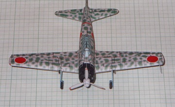


| Model: | Mitsubishi A6M3 Model 32 Type O Naval fighter ("Reisen" or "Zero" -- Allied code name "Zeke") |
| Kit: | ModelArt A6M3 Model 32 |
| Scale: | 1:72 |
| Price: | US$ 3.95, downloaded from Paper Paradise |
| Difficulty: | Medium (3 out of 5) |
| Number of parts: | 117 |
| Instructions: | Good, though brief. A few sentences were apparently garbled during generation of the PDF file. |
| Diagrams: | Excellent. Addition of a 3-view would be helpful. |
| Fit: | Outstanding |
| Coloring: | Excellent, though actual results will depend upon your computer and printer set-up. |
| Resources: | There's a wealth of material about the Zero on the Web, including drawings, photos, and even a sound bite of a low level fly-by. You might try the "WWII Imperial Japanese Navy Aircraft" site at http://www.skypoint.com/members/jbp/ijna/ijnaf.htm, or the "Internet Museum of Imperial Japanese Aircraft" at http://home.interlink.or.jp/~katoh00/. Wayne Cutrell's Photos from the Smithsonian and Mark Johnson's reviews (both referenced on Saul Jacobs's Web site) were helpful. I also used Basil Collier's Japanese Aircraft of World War II (Mayflower Books, New York, 1979). |
Background:
Well over 10,000 Zero's were produced by Mitsubishi and Nakajima for the Imperial Japanese Navy during WWII. The A6M3 was an improved version of the A6M2 Model 21, with a more powerful engine and (in production) without the folding wingtips of the Model 21. The Model 32 was commonly used in the Southwest Pacific from the late spring of 1942. The ModelArt kit represents a plane using the green on grey blotch camouflage scheme common to that theater.
The ModelArt kit:
The design and fit of this 1:72 scale kit is absolutely flawless -- which means that any imperfections in the finished model are pretty much the responsibility of the builder: whether due to choice of paper, quality of printing, errors of commission and omission in construction, or whatever. On the other hand, this jewel of a kit can be purchased as a downloadable PDF file, which provides real security. Mess up an assembly? Just print another copy. I did this frequently: a second attempt at the wing assembly to correct poor glue application the first time; two tries at the spinner (first attempt was just too gross); two tries at the aft fuselage cylinders (I didn't like the glue seams the first time); etc. You get the point. ModelArt kits are extremely dangerous in the hands of perfectionists, and should be locked away from persons with compulsive tendencies.
All that aside, a kit of this accuracy and size requires more than the usual amount of care in building. After a couple of false starts, I began trying to cut on the inside of lines rather than down the middle, for example--especially where the construction lines had no counterpart in the original (e.g., the forward part of the prop spinner). I used Wausau 90# Exact Index card stock for most of the model, but found that lighter weight paper was needed for some of the smaller 3-dimensional pieces. For example, I used a 37# bond for the prop spinner, and regular 20 or 24# bond for the gluing strips used to connect fuselage sections. Each of these requires another pass through the printer, and demonstrates once again the value of downloadable kits.
Some of the parts are truly minuscule. The exhaust ports (which have to be backed on .35 mm card) are 1.0 mm by 0.5 mm ovals! The guns and pitot tube were provided, but I could not roll them to a scale diameter using any paper that would work in my printer. I settled on .032" and .020" brass wire as a substitute.
I felt very little need to color the cut edges on this model. A little sky blue watercolor wash on the cut edges of the landing gear struts was about all that was needed. The fit is excellent; Exact Index card stock is only .007" thick (ideal for this model); and the color scheme is relatively light in tone, making cut edges less noticeable. I used a burnishing tool to round the trailing edges of the wing and tailplanes slightly (see my P-35 review for details), and that helped to eliminate one of the major sources of the "cut edge" problem.
Fuselage:
The fuselage is built up from cylinders with formers and connecting strips. The fit is extremely accurate, and therefore very tight. Dryfitting is essential. Have a sheet of spare parts available.
The cockpit canopy is flawless. Take your time, and butt glue each seam very carefully. Clamp each seam and allow it to dry before moving to the next one.
It's a good idea to drill holes for fuselage machine guns into the front of part #5 before gluing the cowling in place. Cut the gun ports in the cowling before assembly, as well. I waited until the end; and, although, I got it to work, I wasn't happy with the ragged edges I had to fix as a result of trying to do the cutouts at the end.
Empennage:
Rudder and stabilizer assembly is straightforward. I used small pieces of bulkhead scrap to insure a slight airfoil in these pieces. Just be aware that the Zero's stabilizer has no dihedral. Its placement above the mid-line on the fuselage encourages about 10-20 degrees of dihedral if you're not careful.
Wing:
The wing is also straightforward. The main spar is in three sections. Spend some time fitting these before gluing, since this will determine the accuracy of the wing dihedral. There is a single inboard rib for each of the port and starboard wing sections. A separately formed folded tab is used to join the trailing edges. I mounted it slightly inboard of the trailing edge and shaped the T.E. around it for a tighter fit that required no touch-up coloring. Take care in shaping the wing tips. Slight errors here really show up in the finished product. Mounting the fuselage to the wing went off without a hitch.
Landing gear:
Landing gear assembly is straightforward. It can be done without reinforcement, and the resulting assembly, though fragile, is adequate to support the weight of the finished model. I had to go to outside references to find information on positioning of the main gear. This is where a set of 3-views would have helped.
The tail wheel assembly (cut carefully!) is very fragile and weak. I stiffened it with cyanoacrylate glue.
Propeller assembly:
The propeller hub is the only part of the finished model that I'm unhappy with. It's not a problem with the kit, but rather with the size of the parts, and the difficulty of avoiding construction lines showing up in the final assembly. My second attempt was a lot better than the first, but still with construction lines (i.e., cutting lines) visible. I chose not to touch up the prop hub, thinking that the remedy might be worse than the "problem."
I did not build the optional external center mounted fuel tank, mainly because I liked the clean lines of the basic model as is.
Summary:
This is not an easy kit to build; but the difficulty is due to the scale rather than to printing and design, which in this case are as near to perfect as you can get. The kit has 117 parts--on a par with the PMI P-39 and the ModelCard P-35--which are several times the Zero's size at scales of 1:32 and 1:33, respectively. Overall, this is a challenging, but extremely well designed kit. Like Mark Johnson, I was so impressed with it that I bought at least one example of each of the other ModelArt 1:72 models. And now that I've got some experience with the Zero, I'll pick up one or two of the other Zero variants that ModelArt has made available.
Bill Geoghegan
Return to the top of the page


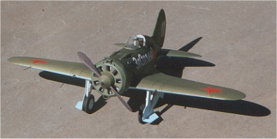
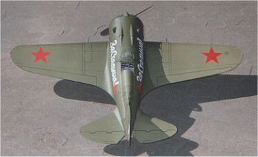

| Model: | Polikarpov I-16 (Variously known as Ishak, Rata or Mosca), probably a Type 24 (1939-40) |
| Kit: | Fly Model #53 (the I-16 is part of a 3 plane package that includes the I-16, IL-2, and Ju-87) |
| Scale: | 1:33 |
| Price: | US $12.00 Plus S&H for the 3-plane package from Paper Models International |
| Difficulty: | Medium (3 out of 5) |
| Number of parts: | Approximately 125 |
| Instructions: | Very brief and in Polish. The more important points can be teased out with the aid of material on the translation page at Saul Jacob's card modeling Web site. |
| Diagrams: | Excellent. They occupy the equivalent of two A4 sheets. |
| Fit: | Good to excellent with one significant exception (see below). |
| Printing: | Fair. There were some color registration problems and blemishes. Printing was much too light on the black and white sheet containing gun and bulkhead patterns, engine detail, etc. These had to be scanned and reprinted to get a good black. Panel lines were nicely scribed, and the cardstock used was very good. |
| Coloring and Artwork: | Good. Only three colors are used (other than black and grey): olive (for Russian topside green), sky blue, and red. This leads to some odd shortcuts -- like having the starboard wingtip light printed sky blue rather than green. Except for the wheel wells, surface detail is fairly sparse. |
| Resources: | A considerable amount of material on the I-16 is available on the Web, including drawings, photos, and detailed writeups that cover almost every variant produced. Good reference sites include the Russian Aviation Museum and the New Zealand Fighter Pilots Museum. The latter was involved in the recovery and reconstruction of six I-16s from Russia, and they host some fantastic photos and written accounts of the plane. Special thanks go to David Okamura, Fred Bultman and Wayne Cutrell for sources and commentary. Peter Ansoff's review of the Möwe I-16 on Saul Jacob's Web site contains a wealth of information about the plane itself, not to mention a great illustration of how to write a review. |
Background:
Nikolai Polikarpov's I-16 heralded a revolutionary new approach to fighter aircraft design when it was introduced in late 1933. It was the first operational cantilever monoplane fighter with fully retractable landing gear; and its performance was near top of the class in comparison to other fighters entering service at that time. It made a worthy showing in the Spanish Civil War, where it was used by Republican forces, and during the early stages of the Sino-Japanese conflict. The I-16 appeared in many variants, and performed in a wide variety of roles. It served as a fighter for several air forces; it was used by the Soviet Union in a ground attack role; it performed as a trainer in both single and two-seat versions; it was carried by Russian heavy bombers as a parasite escort and dive bomber; and it was used late in the war as a high speed reconnaissance aircraft. A few were serving as trainers in Spain as late as the early 1950's. Actual production figures are hard to come by; but estimates range from a low of just over 8,600 to almost 20,000 on the high side.
The I-16 never received an "official" name from the Russian authorities, but it was popularly known as Ishak or "little donkey" -- appropriate given the multitude of roles it was called upon to play. The Spanish Nationalists referred to it by the pejorative Rata ("rat"), which for some unfortunate reason has stuck with it over the years. The Spanish Republicans called it Mosca ("fly"), which seems a little more appropriate. This kit models a Russian plane, however, so I'll stick with Ishak. "Little donkey" it is.
An interesting sidebar to the history of the I-16 concerns the efforts of Tim Wallis, a New Zealand businessman, to find and restore rare Russian aircraft of World War II. Working with the Russian government in the early 1990's, Wallis was able to recover six wrecked I-16's and have them restored to flying condition at one of the original manufacturing facilities in Siberia. (Three Polikarpov I-153's were also restored in a related project sponsored by Wallis.) After being test flown in Russia, all six planes were taken to New Zealand. One will stay in the NZ Fighter Pilots Museum, and the rest will be sold to recover the restoration costs. (I believe one has already been sold to a buyer in California, so it may soon be appearing in Stateside airshows.) This remarkable story of recovery and restoration can be found in a 1998 article available at the NZFPM site.
The Fly Model kit:
I developed a real love-hate relationship with this kit. I liked the subject, the ease with which so much of the kit went together, the fit of most (but not all) components, and diagrams so precise as to make the sparse Polish instructions almost irrelevant. What frustrated me most were the seemingly "minor" design errors that mushroomed into serious assembly problems with some of the most critical components. In other respects the engineering is excellent, and even approaches the precision of computer-assisted designs. But contrasted with this is the marginal quality of some of the printing, and the rework that was required on the non-card sheet of parts. (One of the other kits in this three-pack, the IL-2, had a large area on the upper surface of one wing where ink was incompletely applied, yielding a blotched appearance.) All that aside, the end result is still very pleasing, maybe even "cute," if that can be said of a warplane.
The type of I-16 represented by this kit is somewhat open to question. The gun fairings on the fuselage make it a Type 10 or later. Armament and oil cooler (?) intakes suggest that it is probably a Type 24.
And, finally, as if the designers wanted to make sure that the builder didn't run out of problems to solve, "left" ("L" or lewa) and right ("P" or prawa) are reversed! The "right" wing, for example, is the wing seen on the right when the plane is viewed from the front -- not as seen from the cockpit. (The wing on the seated pilot's right is the "left" wing in this kit.) This caused no end of confusion as I tried to figure out how this kit was supposed to fit together. The other two kits in the three-pack use the standard notation. Go figure....
Fuselage:
The fuselage uses standard segmented construction; adjoining segments are glued bulkhead to bulkhead without connecting strips. The fit is very good, but you can help both accuracy and appearance by test-fitting adjoining bulkheads and making any needed adjustments to shape and taper before attaching the outer skin. Once the skin is fitted and glued, you can lightly sand the bulkhead end on a sheet of fine sandpaper laid flat on your work surface. This helps insure a tight fit with little visible gap between segments.
The cockpit floor and sides make into a separate assembly that is slid into place and glued after being formed. It would be fairly easy to do some extra detailing of controls, cabling, instrument panel, the landing gear winch (the gear was raised and lowered by hand!), etc., before the cabin is glued in place. The detailed cockpit photos on the NZFPM site would be an excellent guide. I settled for a scratchbuilt joystick modeled after the NZ restorations.
Construction of the two forward fuselage segments is a complicated matter. Both of these segments embrace portions of the wheel well assemblies. The forward bulkhead in the second segment also serves double duty as the wing spar and base for mounting the two wheel well assemblies, as shown below:

The engine exhaust ports (which I installed as one of the last steps) were supplied in a roll-up format that looked as though it would present significant problems in shaping, sanding, and coloring. I decided to use J. J. van der Sande's CONE program (version 1.3 is required) to lay out an exhaust port with the correct angle, diameter, and length. I imported the DXF output into Paint Shop Pro 7.0, colored it black, and duplicated it multiple times in a single sheet image (with PSP 7). I printed this out on 47 pound coated paper, and then cut and formed the individual ports on a bamboo skewer (perfect size for a 3mm diameter tube). The black printing was rolled on the inside, and the edges were butt glued. I painted the outside with Floquil gunmetal black. The result matched the shape, thickness and colors of the NZ restorations as well as you could want. These were glued in place with cyanoacrylate so as to protrude approximately .5 mm above the fuselage skin, a best approximation to what was shown in the photos I had available.
The dorsal "hump" (part 7) and the fairing that mates it to the rudder should be installed after the stabilizer and rudder have been glued in place.
Wing:
The wing construction is unusual in that there are no ribs to aid in shaping the airfoil. Tabs on the wing covering, and slots in the fuselage help with shaping, along with gluing tabs on the underside of the wheel well housing. I added a folded gluing strip at the trailing edge to help preserve the airfoil at that point.
The most significant problem was in fitting the underside of the wing covering to the fuselage and wheel well housings. Unfortunately, I cut the opening in one wing on the lines indicated before test-fitting the overall covering; and only then discovered that the wing opening extended beyond the housing by about 2mm, or more than 1/16". I filled these sections in with scrap card and painted over the section to hide the patch. On the other wing, I cut well inside the outline, dry-fitted and trimmed it to shape, and then painted over the remaining white space and construction lines. The problem areas are marked by red ovals in the photo below. A second problem was that one part of the housing extended too far toward the fuselage, into the area exposed by the wing covering. I ended up cutting that section of the housing loose, removing a short section, reshaping and regluing it, before finally attaching the wing covering. The problem area is flagged by the green oval in the picture below. All of this changed the shape of the wheel well, of course, which had a slight (but not too serious) effect on placement of the landing gear assembly. This is what I mean by a "mushrooming" problem.

Empennage: The stabilizer and rudder go together very easily, and a well designed and reinforced spar assembly built into the fuselage bulkhead helps to maintain a proper airfoil. It's probably a good idea to create a folded gluing strip for the trailing edge of each to insure the proper shape. The fairings that mate them to the fuselage fit perfectly.
Nose and propeller assembly: The nose assembly can be tricky, and it requires some advance preparation if you want a rotating propeller. The assembly is formed from two shallow conical segments (about 1/8" or 3mm deep) backed with a bulkhead and fronted with a louver assembly for the air cooled radial engine. A connecting strip is used to mate the two sections. Inside this assembly is the engine mockup (representation of 9 cylinders backed with hardcard and slightly rounded) and the cooling louver. (See picture below.)

Landing gear: Diagrams for the tripod landing gear are quite detailed and very helpful. I used .020" (about .5mm) piano wire for the internal supports, and rolled the struts tight enough to fit snugly on the wire. These were trimmed according to the diagrams, and glued in place without any significant problems. Some adjustment was needed to accommodate changes to the wheel well outline, and 2mm disks were added to axle sections of the wheel struts to lock the wheels in place and permit them to rotate. There is only a single template from which to cut the segments used to build up the wheels, and a draftsman's compass fitted with a knife blade really helps. I had to cut 20 circles out of posterboard to form the two wheels (each about 1/8" thick). The wheels were cut, drilled, glued, sanded, colored and polished before mounting. The wheel well coverings, mounted on the outside of the struts, went into place without a problem. Make sure that the reinforcing wire in the struts extends beyond the end of the strut only enough to insure a secure mounting. If it is too long, it may puncture the upper surface of the wing. Stiffen the bottom of the tailwheel assembly with cyanoacrylate glue before mounting. This will prevent the wheel support from bending sideways.
Windscreen: The windscreen is made up of two frames, each backed with thin acetate (not provided). It is a delicate arrangement, and very difficult to assemble and mount while maintaining the correct curvature. I think a single-piece assembly would have worked better. This is the one part of my finished model with which I am most unhappy. I scanned the windscreen frames and templates, and will probably try to tweak the image and rebuild the component in a single piece.
Final touches: Guns were rolled, colored and installed without a problem. The pitot tube was made from .025" piano wire and painted gunmetal (don't know if this was the right color).
The model required a fair amount of touch-up coloring, mainly with the nose assembly, the undersurface of the wing (where surgery had to be performed) and the usual exposed cut edges. I found it difficult to match the colors used in the kit. The problem, which I hadn't run into with other models, concerned the behavior of paints in different lighting situations. In this instance, the mixture I used for touch-up in the olive drab / topside green areas, worked well in the mix of incandescent and fluorescent light in my work area, but became a much greener color under camera flash and sunlight. (This is apparent in the photos.) I also tried using acrylic paints for the first time on this model, and found that they were too glossy in comparison with the printed card stock. I may decide to go back and redo some of the touch-up work.
I did not install an antenna because I could not tell from the information available how it was configured in the original. Once I find out, I'll put it in. Since I'll probably replace the windscreen, it seems best to leave the antenna off until the rework is complete.
Summary: For all the frustration, I'm pretty satisfied with the result. But it's the kit that frustrates -- the finished model and its original that satisfies. In retrospect, I'm probably getting spoiled by the precision of design, detail, coloring and printing exhibited by the newer computer assisted kit designs from Digital Navy, Halinski, GPM, and others. Fly Model's I-16 is a little more "hand made," and it suffers from a few inaccuracies. When I think about how much of a nightmare this kit must have been to design (wheel wells that transitioned from wing to fuselage, for example), the result is very, very good.
But above all, it's the plane itself that appeals to me. Short, fat, stubby, lots of wing -- it almost looks like a GeeBee with guns. And what other fighter could be known as a rat, a fly or, strangest of all, a little donkey?
Bill Geoghegan
![]() Return to the Card Model Main Page
Return to the Card Model Main Page
This page was created by:
Saul H. Jacobs M.Ed.
Avionics Specialist, United States Air Force (Retired)
Microcomputer Technology, Pima Community College (Retired)
Tucson Arizona
Design of the content of this page is the property of Bill Geoghegan